|
|
|
Categories
|
|
Information
|
|
Featured Product
|
|
|
 |
|
|
There are currently no product reviews.
 ;
This is a good quality scan of the Operation & Maintenance (Service) Manual for the PAL version of this high-band broadcast umatic, BVU-800P
All schematics and lineup procedures appear to be included in this one manual AFAICT.
The file size is just over 113 MB which gives an idea of the quality and number of pages.
All of the schematics, which contain some fairly small print, are easily readable when you zoom into the page.
John Thompson, Newcastle Upon Tyne, England.
;
Good quality, all schematics of few of models. There is also short form of user manual and regulation manual.
;
Perfect copy of the service manual. you can enlarge every page, and it comes up
with all details.
;
It´s very very nice manual with all, what i need. Original in good quality. Very fast business. Very much thanks...
;
Purchased the manual that I was looking for at a great price and could download it easily.. Great service experience and for future purchases I plan to use the site.
Thank you very much
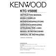
KTC-V500E/N/P
ADJUSTMENT
X25 Circuit Adjustment Specification (M : For the Other Markets) Item
1. Video detection co il adjustment L303
Adjustment method/Adjustment value
1. Turn VR301 [RF-AGC] fully to the right. 2. Apply DC2.0V to TP [IF AGC] (IC300 pin36). 3. Feed fo=38.0MHz, Mod=1kHz, AM60%, Level=100dBµ into TP [IF] (A100 pin8). 4. Observe the TP [VIDEO] (IC300 pin8) waveform on an oscilloscope and adjust L303 for maximum level.
Conditions
No ANT signal If the waveform is clipped, slightly increase the DC voltage. AC range
Maximum
2. Audio detection coil adjustment L300
1. Turn VR301 [RF-AGC] fully to the right. 2. Feed fo=31.5MHz, No Modulation, Level=94dBµ into TP [IF] (A100 pin8). 3. Connect a voltmeter to TP [SIF] (both ends of R314) and adjust L300 for 0V ± 0.01V.
No ANT signal
3. S-METER adjustment VR300 4. RF AGC adjustment VR301
1. Turn VR301 [RF-AGC] fully to the right. 2. Feed a 30dBµ CHINA 9CH color bar RF signal into the ANT input terminal. 3. Audio (P/S ratio -6dB) no modulation. 4. Connect a voltmeter to CN300 and adjust VR300 [SMET] so it reads 3.5V ± 0.05V. 5. Set the RF signal to 70dBµ and adjust VR301 [RF-AGC] so that the voltmeter connected to CN300 reads 4.8V ± 0.05V.
Postpone adjusting VR301 to prevent AGC having effect at 30dBµ. Ensure the RF AGC adjustment is performed after the S-METER adjustment. No ANT signal Test mode
5. Diversity free run frequency adjustment VR400
1. Connect a frequency counter to CN400. 2. Using the remote control unit TV/NAVI button, switch to adjustment mode. 3. Adjust VR400 [15kHz] so as to obtain 15625 ± 100Hz.
6
|
|
|
> |
|