|
|
|
Categories
|
|
Information
|
|
Featured Product
|
|
|
 |
|
|
There are currently no product reviews.
 ;
Readable text and good copy. Very much needed if you wish to do some repairs on this fine old unit.
;
Fint forløb med levering af manualen. Kvaliteten af skanningen betegnes som middel
 ;
I found the manual to be clear concise and complete. It was of immense assistance when removing the unit as the unit was over 22 years old and the wiring diagram was unobtainable from the manufacturer. The exploded drawings were clear as were the instructions and labels.
;
I will highly recommend this seller. They are honest, accurate, fast and responsible.
;
This manual was very good & was very helpful with repairs.
Always great & fast service from Owner's manual.
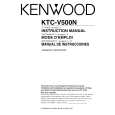
KTC-V500E/N/P
ADJUSTMENT
X25 Circuit Adjustment Specification (M : For the Other Markets) Item
1. Video detection co il adjustment L303
Adjustment method/Adjustment value
1. Turn VR301 [RF-AGC] fully to the right. 2. Apply DC2.0V to TP [IF AGC] (IC300 pin36). 3. Feed fo=38.0MHz, Mod=1kHz, AM60%, Level=100dBµ into TP [IF] (A100 pin8). 4. Observe the TP [VIDEO] (IC300 pin8) waveform on an oscilloscope and adjust L303 for maximum level.
Conditions
No ANT signal If the waveform is clipped, slightly increase the DC voltage. AC range
Maximum
2. Audio detection coil adjustment L300
1. Turn VR301 [RF-AGC] fully to the right. 2. Feed fo=31.5MHz, No Modulation, Level=94dBµ into TP [IF] (A100 pin8). 3. Connect a voltmeter to TP [SIF] (both ends of R314) and adjust L300 for 0V ± 0.01V.
No ANT signal
3. S-METER adjustment VR300 4. RF AGC adjustment VR301
1. Turn VR301 [RF-AGC] fully to the right. 2. Feed a 30dBµ CHINA 9CH color bar RF signal into the ANT input terminal. 3. Audio (P/S ratio -6dB) no modulation. 4. Connect a voltmeter to CN300 and adjust VR300 [SMET] so it reads 3.5V ± 0.05V. 5. Set the RF signal to 70dBµ and adjust VR301 [RF-AGC] so that the voltmeter connected to CN300 reads 4.8V ± 0.05V.
Postpone adjusting VR301 to prevent AGC having effect at 30dBµ. Ensure the RF AGC adjustment is performed after the S-METER adjustment. No ANT signal Test mode
5. Diversity free run frequency adjustment VR400
1. Connect a frequency counter to CN400. 2. Using the remote control unit TV/NAVI button, switch to adjustment mode. 3. Adjust VR400 [15kHz] so as to obtain 15625 ± 100Hz.
6
|
|
|
> |
|