|
|
|
Categories
|
|
Information
|
|
Featured Product
|
|
|
 |
|
|
There are currently no product reviews.
 ;
I am a vintage hifi collector. No way to fix that device without the appropriate service manual...thanks to your site I got it and every thing is easier now. I got the manual right after ordering: fast cheap accurate ... thank you
;
Wonderful job clear. Qick fantastic. These people are really good. If even a problem arise they are wonderful assisting you. These scheme is so net despite this is a very old TV. Thank you for everything!!!!!!!!
;
Detailed schematic diagram, manual for professionals
;
Good service manual,exploded view,adjusment and test point locations,head alignment,mechanical checks and adjusments,all perfect.
;
Block diagram,play rec block diagram,adjusments, it's a very good well done repair manual.
SECTION 3 SET-UP ADJUSTMENTS
� � The following adjustments should be made when a complete realignment is required or a new picture tube is installed. These adjustments should be performed with rated power supply voltage unless otherwise noted. Perform the adjustments in order as follows : 1. Beam Landing 2. Convergence 3. Focus 4. White Balance Note : Test Equipment Required. 1. Color-bar/Pattern Generator 2. Degausser 3. Oscilloscope
Controls and switch should be set as follows unless otherwise noted: PICTURE control ........................................................... normal BRIGHTNESS control ................................................... normal
.................................................................................................................................................................................................................................
Preparations : � In order to reduce the influence of geomagnetism on the set's picture tube, face it east or west. � Switch on the set's power and degauss with the degausser.
Purity control
3-1. BEAM LANDING
1. Input the white raster signal with the pattern generator. Contrast Brightness normal
}
Fig. 3-2
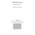
2. Set the pattern generator raster signal to green. 3. Move the deflection yoke to the rear and adjust with the purity control so that the green is at the center and the blue and the red take up equally sized areas on each side. (See Figures 3-1 through 3-3.) 4. Move the deflection yoke forward and adjust so that the entire screen is green. (See Figure 3-1.) 5. Switch the raster signal to blue, then to red and verify the condition. 6. When the position of the deflection yoke has been decided, fasten the deflection yoke with the screws. 7. If the beam does not land correctly in all the corners, use a magnet to adjust it. (See Figure 3-4.)
BLUE
RED
GREEN
Fig. 3-3
Purity control corrects this area. Disk magnets or rotatable disk magnets correct these areas (a-d).
Deflection yoke positioning corrects these areas. b
c a
Fig. 3-1
d
Fig. 3-4
� 11 �
|
|
|
> |
|