|
|
|
Categories
|
|
Information
|
|
Featured Product
|
|
|
 |
|
- Specifications
- Connectors
- Self Diagnostic Software
- GENERAL
- Switching On the TV and Automatically Tuning
- Introducing the Menu System
- Teletext
- Connecting Optional Equipment
- Using Optional Equipment
- Troubleshooting
- DISASSEMBLY
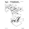
- Rear Cover Removal
- A Board PWB Removal 1
- A Board PWB Removal 2
- Service Position
- Wire Dressing
- Picture Tube Removal
- Rear Cover Removal
- Chassis Removal
- Service Position
- Wire Dressing
- Picture Tube Removal
- SET - UP ADJUSTMENTS
- Beam Landing
- Convergence
- Focus Adjustment
- Screen (G2), White Balance
- CIRCUIT ADJUSTMENTS
- Electrical Adjustments
- Test Mode 2
- DIAGRAMS
- Circuit Board Location
- Block Diagrams
- Schematic Diagrams and Printed Wiring Boards
- Semiconductors
- IC Blocks
- EXPLODED VIEWS
- Chassis (KV - 21LT1)
- Chassis (KV - 21FT2)
- Picture Tube (KV - 21LTl)
- Picture Tube (KV - 21FT2)
- ELECTRICAL PARTS LIST
There are currently no product reviews.
 ;
This scanned manual is well done in that most all the pages except for one is straight and clear- the way I would do them. One page was upside down but that happens. For the money that is charged on this site you get a pretty good deal. Now with complex repairs, I still prefer to us paper manuals which I have to buy at stereomanuals but the one I got here was much less than the $45 he was charging but this is a larger than normal manual for three different units. I am a picky manual user because I have used original manuals from Sony and Teac.
;
Very useful service manual, was exactly what i needed.Good quality,reasonable price.Thank you.
;
Acurate informations inside the SM and I could repair my old Sansui SC-3330 without any problems. Thanks.
;
I used it to repair a NAD 7030, but unfortunately, the 7045 is different !
But documentation was useful.
;
Content A4 and A3 format pages. Exactly what I needed to restore my old receiver.
Layout of each control
3-4. Screen (G2), White Balance
[Adjustment in the service mode using the remote commander] G2 adjustment 1. 2. 3. Input a dot signal from the pattern generator. Set the Picture, Brightness and Colour to minimum. Apply 175V DC from an external power supply to the R, G and B cathodes of the CRT. Whilst watching the picture, adjust the G2 control [SCREEN] located on the Flyback Transformer to the point just before the flyback return lines disappear. White balance adjustment for TV mode 1. 2. Input an all-white signal from the pattern generator. Enter into the �Service Mode� by pressing �TEST�, �TEST� and �MENU� on the Service Commander. 3. Select �Service� from the on screen menu display and press the right arrow button on the remote commander. 4. The �Service� menu will appear on the screen. [See Page 18] 5. Set the �Contrast� to MAX. 6. Set the �R-Drive� to 25. 7. Adjust the �G-Drive� and the �B-Drive� so that the white balance becomes optimum. 8. Press the �OK� button to write the data for each item. 9. Set the �Contrast� to MIN. 10. Adjust the �G-Cutoff�, and the �R-Cutoff� with the left and right buttons on the remote commander so that the white balance becomes optimum. 11. Press the �OK� button to write the data for each item.
V.STAT
Purity BMC (Hexapole)
4.
3-3. Focus Adjustment
1. 2. 3. Receive a television broadcast signal. Normalize the picture setting. Adjust the focus control located on the flyback transformer to obtain the best focus at the centre of the screen. Bring only the centre area of the screen into focus, the magenta-ring appears on the screen. In this case, adjust the focus to optimize the screen uniformly.
Focus
Screen
17
|
|
|
> |
|