|
|
|
Categories
|
|
Information
|
|
Featured Product
|
|
|
 |
|
|
There are currently no product reviews.
 ;
Very good documentation for the Grundig 2077 model (as well as similar 800/900/1000 series radios). The first two pages are a summary of reception specifications and output capability. The third page is the tuner dial indicator and dial cord routing diagram. the final ~5 pages are the schematics for the various models (including 2077). The scan quality of the schematics are good, adn can be easily read if zoomed in. The documents are in German, not English as stated. It would have been nice to have the tuning sequence and settings, and some trouble shooting materials... or component and wiring map.
 ;
Perfect like it was descriped, Perfect like it was descriped
;
Very good detail, all pages clear, exactly what I needed
;
Excellent service, and just what I needed to service my TU-7700. All pages of the manual are clear and easily readable.
;
Excellent printing quality.
A complete and very usefull service manual with all details.
GREAT SERVICE AT VERY LOW PRICE!
A+++++++++++++++++++++++++
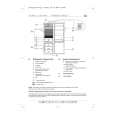
KV-27S42/27S46/27S66/29AL42/29AL42C/29AL66/ 29AL66C/29SL42/29SL42C/29SL46/29XL42M
SECTION 3 SET-UP ADJUSTMENTS
The following adjustments should be made when a complete realignment is required or when a new picture tube is installed. These adjustments should be performed with rated power supply voltage unless otherwise noted. Set the controls as follows unless otherwise noted. VIDEO MODE: STANDARD PICTURE control: ................ Normal BRIGHTNESS control ......... Normal Perform the adjustments in order as follows: 1. Beam Landing 2. Convergence 3. Focus 4. Screen (G2) 5. White Balance Note: Test equipment required: � � � � Color bar pattern generator Degausser DC power supply Digital multimeter
3-1. BEAM LANDING
Before beginning adjustment procedure: 1. Degauss the entire screen. 2. Feed in the white pattern signal.
5. Move the deflection yoke forward and adjust so that the entire screen becomes green.
Adjustment Procedure
1. Input a raster signal with the pattern generator. 2. Loosen the deflection yoke mounting screw and set the purity control to the center as shown below.
Purity Control
6. Switch over the raster signal to red and blue and confirm the condition. 7. When the position of the deflection yoke is determined, tighten it with the deflection yoke mounting screw. 8. If landing at the corner is not right, adjust by using the disk magnets.
3. Turn the raster signal of the pattern generator to green. 4. Move the deflection yoke backward and adjust the purity control so that green is in the center and red and blue are at the sides evenly.
Purity control corrects this area
a c
b d
Disk magnets or rotatable disk magnets correct these areas (a-d)
Blue
Red
Deflection yoke positioning corrects these areas
Green
c b d
a
� 14 �
|
|
|
> |
|