|
|
|
Categories
|
|
Information
|
|
Featured Product
|
|
|
 |
|
|
There are currently no product reviews.
 ;
This manual is all I need to check and repair my equipment. Thank you....
;
This manual is all I need to check and repair my equipment. Thank you....
;
This manual is all I need to check and repair my equipment. Thank you....
;
this manual make me repair my vintage radio with easily.
Thank you for your best service
sukpra
;
A good manual. Had everything i needed to make the repair.
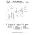
SERVICE MANUAL
Chassis No. SCC-A05P-A
US Model
Canadian Model
Chassis No. SCC-A50G-A
+
Note: The service manual for RM-757 has been issued separately.
MODELS OF THE SAME SERIES
KV-27TR21
American TV standards VHF: 2-13 UHF: 14-69 Cable TV: 1-125 Picture tube Microblack Trinitron tube 27-inch picture measured diagonally 28inch picture tube measured diagonally Input VIDEO INPUT (phono jacks) Video: 1 Vp-p, 750hms unbalanced, sync negative Audio: 500 rnVrms (100% modulation) Impedance: 47 kilohms Output AUDIO OUTPUT (VARIABLE) (phono jacks) More than 408 mVrms at the maximum volume setting (variable) (100% modulation) Impedance: 10 kilohms Power requirements 120 V AC, 60 Hz Power consumption 160W (max.) 5W (in standby condition) Dimensions Approx. 672 x 650 x 524.5 m m (w/h/d) Weight 49Kg Sound output 3W x 3W (music power)
Television system Channel coverage
Accessories supplied Remote Commander RM-757 with 2 size AA batteries Antenna connector . Optional accessories UIV mixer E A C S Connecting cord VMC-810Sl820S R K-C741150 Design and specifications subject to change without notice.
|
|
|
> |
|