|
|
|
Categories
|
|
Information
|
|
Featured Product
|
|
|
 |
|
|
There are currently no product reviews.
 ;
Very good quality, prompt response. This website has reasonable prices and wide range of manuals that are hard to find.
;
The document was usefull, and it was exactly what I was looking for.
;
OK?..manual is complet and helpfull... for repairing such a old and rare boombox like JVC PCM it is necessary...
;
Super Anleitung. Ordentliche Auflösung. Das ganze noch in Deutsch wäre zu schön. Alle Datenblätter sind sauber Kopiert und alle Leitungswege sind sauber ausgeführt
;
Thanks God for the internet and thanks for the service like this - proffessional solution on time.
KV-32HS510/34DRC510/34HS510/36HS510/38DRC510
1-4. PICTURE TUBE REMOVAL
WARNING: BEFORE REMOVING THE ANODE CAP High voltage remains in the CRT even after the power is disconnected. To avoid electric shock, discharge CRT before attempting to remove the anode cap. Short between anode and CRT coated earth ground strap. 1 8
Coated Earth Ground Strap
11 9
7 6
3 4
1. Discharge the anode of the CRT and remove the anode cap. 2. Unplug all interconnecting leads from the deflection yoke, neck assembly, degaussing coils and CRT grounding strap. 3. Remove the Sub-Woofer Assemblies. 4. Remove the CX Board from the CRT. Remove the chassis assembly. Loosen the neck assembly fixing screw and remove. Loosen the deflection yoke fixing screw and remove. Place the set with the CRT face down on a cushion and remove the degaussing coil holders. 9. Remove the degaussing coils. 10. Remove the CRT grounding strap and spring tension devices. 11. Unscrew the four CRT fixing screws [located on each CRT corner] and remove the CRT [Take care not to handle the CRT by the neck]. 5. 6. 7. 8.
2
10
5
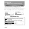
ANODE CAP REMOVAL PROCEDURE
WARNING: High voltage remains in the CRT even after the power is disconnected. To avoid electric shock, discharge CRT before attempting to remove the anode cap. After removing the anode cap, short circuit to either the metal chassis, CRT shield, or carbon painted on the CRT. NOTE: After removing the anode cap, short circuit the anode of the picture tube and the anode cap to either the metal chassis, CRT shield or carbon painted on the CRT.
REMOVAL PROCEDURES
c
a
b
Anode Button
Turn up one side of the rubber cap in the direction indicated by arrow a .
Use your thumb to pull the rubber cap firmly in the direction indicated by arrow b .
HOW TO HANDLE AN ANODE CAP
1. Do not use sharp objects which may cause damage to the surface of the anode cap. 2. To avoid damaging the anode cap, do not squeeze the rubber covering too hard. A material fitting called a shatter-hook terminal is built into the rubber. 3. Do not force turn the foot of the rubber cover. This may cause the shatter-hook terminal to protrude and damage the rubber.
When one side of the rubber cap separates from the anode button, the anode cap can be removed by turning the rubber cap and pulling it in the direction of arrow c .
� 12 �
|
|
|
> |
|