|
|
|
Categories
|
|
Information
|
|
Featured Product
|
|
|
 |
|
|
There are currently no product reviews.
 ;
SATELLIT 4000 GRUNDIG
Service Manual
high quality. good graphics. prompt service.
;
Excellent printing quality.
A complete and very usefull service manual with all details.
GREAT SERVICE AT VERY LOW PRICE!
A+++++++++++++++++++++++++
;
Excellent printing quality.
A complete and very usefull service manual with all details.
GREAT SERVICE AT VERY LOW PRICE!
A+++++++++++++++++++++++++
;
Excellent printing quality.
A complete and very usefull service manual with all details.
GREAT SERVICE AT VERY LOW PRICE!
A+++++++++++++++++++++++++
;
Excellent printing quality.
A complete and very usefull service manual with all details.
GREAT SERVICE AT VERY LOW PRICE!
A++
SECTION 3 DISASSEMBLY
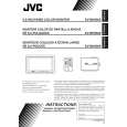
3.1 Monitor unit section 3.1.1 Removing the bottom cover aseembly (See Fig.1) (1) Remove the four screws A attaching the bottom cover assembly on the back of the monitor unit. (2) Release the two claws a attaching the bottom cover assembly.
Claw a
Bottom cover assembly
Claw a
A
Fig.1 3.1.2 Removing the monitor board (See Fig.2) � Prior to performing the following procedure, remove the bottom cover aseembly. (1) Disconnect the three connectors J2, J3 and M3 on the monitor board. (2) Remove the four screws B attaching the monitor board. (3) Remove the solder from the PVC wire b on the jack board. 3.1.3 Removing the jack board (See Fig.2 to 3) � Prior to performing the following procedure, remove the bottom cover aseembly and remove the monitor board aseembly. (1) Remove the two screws C attaching the jack board on the back of the monitor uboard. (2) Remove 11 solders b on the jack board.
A
Monitor board
M3 Jack board Solders b J2 J3
B
Fig.2
PVC wire b
B
Monitor board
Jack board
C
Fig.3
(No.49795)1-5
|
|
|
> |
|