|
There are currently no product reviews.
 ;
hi .full information for JVC GRVF1EG Service Manual its compete .Thank You
 ;
perfect and good copies, all good readable.
within 24hrs and very cheap also.
;
Great salespeople, muuito attentive recommend everyone buy this site.Obrigado by atendomento..
;
everything was fine - fast, readable, worth the price
;
I'm happy to get a manual from this rare old amp. The pdf is from good qualty.
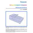
1. The Hopper Plate is placed onto the Hopper Shaft ( above figure.
) not shown in the
2. The Hopper Arm 1 is coupled to a pin on the Main Chassis at the front side of the Hopper, so that it can oscillate freely, and the Hopper Arm 2 is coupled to a pin on the Main Chassis at the rear side of the Hopper ( part) in the same way, and in both cases the other end is coupled to the Hopper Shaft. 3. The Hopper rack is installed to the Hopper Arm 1 so that a part of the gear with the center at the oscillating support is engaged, and at the gear side, this rack is engaged with the Hopper Motor not shown in the figure. 4. The pin of the Hopper Arm 2 is engaged with the elongated hole at the intermediate part of the Hopper Arm 1, and when the Hopper Motor runs in counterclockwise direction as seen from the output shaft, the rack mentioned above oscillates in upward direction with the support of the Hopper Arm 1 at the center, and the front side of the Hopper Plate rises. Movement in arrow ( ) direction.
5. When the Hopper Arm 1 exceeds the position where the elongated hole comes into contact with the pin of the Hopper Arm 2, the Hopper Arm 2 is coupled with the Hopper Arm 1, moves up with the support at the center, and the rear edge of the Hopper Plate moves up. 6. By this series of operations, the Hopper Plate posture changes from the bottom position via an intermediate inclined posture to a level posture, and
30
|