|
|
|
Categories
|
|
Information
|
|
Featured Product
|
|
|
 |
|
|
There are currently no product reviews.
 ;
Good manual. It is complete and of high quality, both text and graphics. The schematics are with the original big size, so it can be viewed or printed without any loss of resulution and sharpness.
;
We needed a manual quickly...online it was available immediately, at a very low price. We loved the convenience!
;
Excellent!!
Got what I need and very fast!!
Thank You
;
One address for rare manuals.Very good copy. Thank you.
Your
Klaus Husse
;
All ok. I pay 5 $ and now i have 92 pages of good scaned service manual for my oooooold akai. Now i will try to repair it.
KV-XA29M31/XA29M50/ XA29M61/XA34M31
RM-954
4-4. G2 (SCREEN) AND WHITE BALANCE ADJUSTMENTS
1. 1) 2) 3) G2 (SCREEN) ADJUSTMENT Set the PICTURE to normal. Put to VIDEO input mode without signals. Connect R, G and B of the C6 board cathode to the oscilloscope. 4) Adjust BRIGHTNESS to obtain the cathode voltage to the value below. 5) Adjust G2 (screen) on the FBT until picture shows the point before cut off.
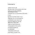
2. WHITE BALANCE ADJUSTMENT 1) Set to Service Mode (Refer Section 5-1: ADJUSTMENTS WITH COMMANDER). 2) Input white raster signal. 3) Set the PICTURE to minimum. 4) Select GCT (WHB 4) and BCT (WHB 5) with [1] and [4], and adjust the level with [3] and [6] for the best white balance. 5) Set the PICTURE to maximum. 6) Select GDR (WHB 1) and BDR (WHB 2) with [1] and [4], and adjust the level with [3] and [6] for the best white balance. 7) Write into the memory by pressing [MUTING] then [0]. 3. SUB BRIGHT ADJUSTMENT 1) Set to service mode. 2) Input a staircase signal of black to white from the pattern generator. 3) BRIGHTNESS .... 50%. PICTURE ............ MINIMUM 4) Select SBR (WHB7) with [1] and [4], and adjust SBR (WHB7) level with [3] and [6] so that the second stripe from the right is dimly lit.
Cathode setting voltage: 180 V ± 2 (VDC)...29" 175 V ± 2 (VDC)...34"
0V
White second from the right
Black
� 34 �
|
|
|
> |
|