|
There are currently no product reviews.
 ;
It is pretty good. The schematics were covered all components, the manual also provide the parts list . It's useful for the trouble shooting.
 ;
Very fast service, best quality of the service manual and the schematics
;
This service manual of the old video cassette recorder VT-LC50EM is very good readable even the tiniest numbers (i.e. IC-pins). The circuits are very clear. Many details of the schematic are very good described but in GERMAN language. Many schematic details - but complete at all. Common background information of several details are enclosed and physical knowledge of the TFT liquid crystal display for example. The manual lacks PCB drawings. If you understand german I would recommend this manual for you.
;
Hi, this is a very clear manual, nice copy, not quite up to the standard of the very best available but better than many others. I think the price was especially fair for a hard to find manual and I would certainly use this manual seller again. Recommended.
;
This schema available for me in good condition. I would highly recommend.
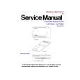
System reset uses the power monitor IC to monitor the +5 V power supply to the main board. If the supply voltage reaches 4.75 V or above, after a time lag of approximately 180 ms due to the time constant of the R.C., the reset signal is changed from L -> H (RSTn). This signal is received by IC136, then input to the CPU (IC101), flash memory (IC102), RTC (IC128), the flash memory card (master) and the flash memory card (slave). To prevent current intake, IC136 uses the CMOS IC. Simultaneously, the reset signal (RST) inverted at IC109 is input to DSP IC120A (Ach), DSP IC120B (Bch), and gate array IC125. KX-TVS50-1 Reset IC Expanded Time Calculation Expanded time (tPLH) = CI � RL � (In (Vcc ÷ (Vcc - (Vs CPU + 0.2)))) + 0.04(ms) CL: F RL: k Voltage: V Vs CPU: CPU reset threshold voltage
Measured Value Graph 1
29
|