|
|
|
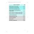
Categories
|
|
Information
|
|
Featured Product
|
|
|
 |
|
|
There are currently no product reviews.
 ;
FAST very good and clear a great unexpensive job!!! very recomended for all people who are preofessional or hobbists as me!!!!!!
 ;
Thank you very much for this Service Manual, it helped us a lot to repair the M-4318!
...BUT: The parts list is missing and the free parts katalog on web isn't complete, so now we don't know the part numbers of the defect parts :(
We had to build them out of a working machine, and need the numbers to reorder the missing parts now.
;
Very good manual with clear electrical diagrams. Thanks owner-manuals.
;
Great manual, thank you, sony kp46s3 service manual perfectly, i am very happy.
;
Complete original Service Manual in good (scan) quality!
SECTION 4 MECHANISM ADJUSTMENTS
PRECAUTION 1. Clean the following parts with a denatured-alcohol-moistened swab: record/playback head pinch roller erase head rubber belts capstan idlers 2. Demagnetize the record/playback head with a head demagnetizer. 3. Do not use a magnetized screwdriver for the adjustments. 4. After the adjustments, apply suitable locking compound to the parts adjusted. 5. The adjustments should be performed with the rated power supply voltage unless otherwise noted. � Torque Measurement Mode Forward Forward Back Tension Reverse Reverse Back Tension FF, REW Torque Meter CQ-102C CQ-102C CQ-102RC CQ-102RC CQ-201B Meter Reading 36 to 61g�cm (0.50 � 0.84 oz�inch) 2 to 6g�cm (0.026 � 0.082 oz�inch) 36 to 61g�cm (0.50 � 0.84 oz�inch) 2 to 6g�cm (0.026 � 0.082 oz�inch) 61 to 143g�cm (0.85 � 1.98 oz�inch)
SECTION 5 ELECTRICAL ADJUSTMENTS
DECK SECTION 0 dB=0.775 V
1. Demagnetize the record/playback head with a head demagnetizer. (Do not bring the head demagnetizer close to the erase head.) 2. Do not use a magnetized screwdriver for the adjustments. 3. After the adjustments, apply suitable locking compound to the parts adjust. 4. The adjustments should be performed with the rated power supply voltage unless otherwise noted. 5. The adjustments should be performed in the order given in this service manual. (As a general rule, playback circuit adjustment should be completed before performing recording circuit adjustment.) 6. The adjustments should be performed for both L-CH and Rch. 7. Switches and controls should be set as follows unless otherwise specified. 8. Set to test mode. (Press key switch same time GROOVE ENTER/NEXT and DISC 4 � Test Tape Tape P-4-A100 WS-48B P-4-L300 Signal 10 kHz, �10 dB 3 kHz, 0 dB 315 Hz, 0 dB Used for Azimuth Adjustment Tape Speed Adjustment Level Adjustment button.)
� Tape Tension Measurement Mode Forward Reverse Tension Meter CQ-403A CQ-403R Meter Reading more than 100 g (3.52 oz) more than 100 g (3.52 oz)
Record/Playback Head Azimuth Adjustment DECK A DECK B Note: Perform this adjustments for both decks Procedure:
test tape P-4-A100 (10KHz, �10dB) main board CN207 Pin 1 (L-CH) Pin 3 (R-CH) level meter set main board CN207 Pin 2 + �
� 32 �
|
|
|
> |
|