|
|
|
Categories
|
|
Information
|
|
Featured Product
|
|
|
 |
|
|
There are currently no product reviews.
 ;
Nice to have the service manual for the Sony DCR-TRV345E now. The document is of excellent quality.
 ;
MACKIE HR824 26 pages English-only Service Manual contains:
1) HR824 technical overview with the description of front and rear panel switches.
2) HR824 specs
3) Block Diagram
4) Wiring Diagram
5) Packaging management
6) Spare part & final assembly list (for PCB rev A and B) + exploded view
7) Test Procedures (where, how to measure voltage...) including Test Point diagram on the PCB.
8) IC and Transistor charts.
Excellent guide: very clear, good scan quality enabling us to print readable diagram :-)
Note:
Mackie HR824 make extensive use of surface mount devices (SMD). Service on the HR824 must
only be undertaken by experienced service technicians with the right tools, experience and patience to perform surface mount rework when needed.
;
This Service manual is very well scanned and its clean to read, no any anti-theft words that un-english could understand. I got my CCD600 working with this manual and it´s clear shematics :)
;
I was very pleased with the service provided and was surprised at how good the quality was of the manual. I thought it may be a third generation copy or so, but it is as good as the websites that charge 3 times this much. I repair some electronics for family and friends without charge, so this is perfect for me. Thank you very much.
;
The service was great and the document was also great. Highly recommend!!!!
If anyone has a users manual... Please email me. need one. $ [email protected]
LC-13B2E
ADJUSTING PROCEDURE OF EACH SECTION
[1] Entering the MAIN side adjustment process mode
There are three methods below. 1) Press the �Adjustment process key� on the remote control after turning on the power. 2) Pressing both the MENU key and the TV/VIDEO key on the main body, turn on the power. Then, press the volume DOWN key and the tuning DOWN key at the same time. 3) Turn on the power with falling either KEY4 (pin (81) of microprocessor) or KEY5 (pin (82) of microprocessor) to �L�. [Note] For the method 3), the ROM is initialized at the same time. Therefore, 3) must be executed, if IC2004 or IC2001 is changed. For 1) or 2), the main body only enters the MAIN side adjustment process.
[2] Entering the TUNER side adjustment process mode
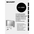
4) Entering the TUNER side adjustment process MENU key on the main body � Cursor UP key (remote control) � Select the position shown in the figure below and press the M key (remote control) within 1 second. � Enters the adjustment process.
Direct control at TV
Black level Contrast Colour
: select
M: Back E: End
[3] Adjustment
MAIN side adjustment (Press the �M� key to move the cursor and press the volume UP/DOWN key to make an adjustment.) � Power supply voltage adjustment (+B 5V) � Model setting � Inch size setting � COMMON BIAS adjustment of LCD module � CUTOFF adjustment TUNER side adjustment (Press the tuning UP/DOWN key to move the cursor and press the volume UP/DOWN key to make an adjustment.) � Horizontal size adjustment (LCD adjustments) � Video adjustment (other adjustments) Y delay Subcontrast Subcolour Subbrightness Tint offset AGC gain start The TUNER side adjustment is possible. However, it is recommended to replace EAROM (I2).
9
|
|
|
> |
|