|
There are currently no product reviews.
 ;
It was very usefull, it is clear the quality is super, the price I paid is very afordable.
Generally speaking Iam very happy with this company.
;
The manual was exactly what I needed, Good quality scans too. superb.
;
I am so happy found this site as it consists of so many Manuls and easy to aquire. This onei s exactly what I wanted and much more as it has info on not only how to use the tuner but how to repair it as well. I will come here 1st before purchasing else where! Thanks owner-manual.com!
;
Top class product, I printed it out on A3 paper and it is clear and very easy to follow.
Cheaper than buying a new radio!
;
is part of the manual is very useful for repairing
Here are circuit diagrams
if there is damage, I recommend using this part of the
a complete list of circuit boards and components
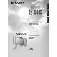
LC-15B5H
12. Remove the two lock screws from the inverter PWB, and detach the inverter PWB. 13. Remove the one lock screw from the card frame cover over, and detach the card frame cover. 14. Remove the five lock screws from the main PWB, and undo the claw a. Detach the main PWB by lifting the area around the claws and pulling the PWB out. 15. Remove the five lock screws from the analog PWB, and undo the claws b and c. Detach the chassis frame (right) from the analog PWB by pulling out the terminals. In the same way, undo the claws d and e, and detach the chassis frame (left) from the analog PWB by pulling out the terminals. Note: When detaching the main PWB and analog PWB, be careful not to break the PWB-fixing claws. 16. Remove the one lock screw from the card LED PWB, and detach the card LED PWB. 17. Remove the four lock screws from the LCD panel unit, and detach the LCD panel unit.
15 15 13 14
Main PWB Analog PWB
14
a
d
Chassis Frame (L) b Card Frame Cover
12
16
c Chassis Frame (R)
e
Card LED PWB Inverter PWB
17
10
|