|
|
|
Categories
|
|
Information
|
|
Featured Product
|
|
|
 |
|
|
There are currently no product reviews.
 ;
Readable text and good copy. Very much needed if you wish to do some repairs on this fine old unit.
;
Fint forløb med levering af manualen. Kvaliteten af skanningen betegnes som middel
 ;
I found the manual to be clear concise and complete. It was of immense assistance when removing the unit as the unit was over 22 years old and the wiring diagram was unobtainable from the manufacturer. The exploded drawings were clear as were the instructions and labels.
;
I will highly recommend this seller. They are honest, accurate, fast and responsible.
;
This manual was very good & was very helpful with repairs.
Always great & fast service from Owner's manual.
LC-20A2H LC-20A2M
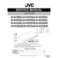
REMOVING OF MAJOR PARTS
1. Detach the terminal cover. 2. Remove the four lock screws from the table stand. 3. Remove the four lock screws each from the left and right speakers. Disconnect the connectors and detach the speaker assemblies. 4. Remove the ten lock screws from the terminals. 5. Remove the five lock screws from the cabinet B. 6. Undo the nine hooks off the cabinet B: Press the hook 6-1 first and then the hooks 6-2 thru 6-9 in this order. Detach the cabinet B. 7. Undo the six wire holders and peel off the 9 pieces of tape. Disconnect the connection cables. (Note: Some pieces of tape are located below the PWBs. To access such tape, detach the PWBs, peel off the tape and disconnect the cables.) 8. Disconnect the connectors from the PWBs.
3
Speaker Assembly (Right)
3 5 4
6-4 6-5 6-6 6-3
Speaker Assembly (Left)
Terminal Cover
1
6-2
Cabinet B Cabinet A
6-7
6-1
6-8
2
6-9
Table Stand (Cover)
Table Stand
SC7001
Tape
8(MAIN Unit)
SC1202 P755 P2001
SC1201
SC401
(Y/C SEPARATION Unit)
7
(INVERTER Unit)
P7755
P7753
8
7
Speaker (Left) Connection Cable Tape
8 8
8
Speaker (Right) Connection Cable Tape
P754
P7102
P7101 P7301
P753
P7751 P701
Terminal PWB Holder 7
Tape
8
SC3401
P303 SC3405
P7305
(TERMINAL Unit)
P3701
P3206
7
7
Tape
(OPERATION Unit) P4004
7
Tape
6
|
|
|
> |
|