|
|
|
Categories
|
|
Information
|
|
Featured Product
|
|
|
 |
|
|
There are currently no product reviews.
 ;
In a word AWESOME.
I never expected the quality and abundant content that I got with this manual. Everything you'd ever want to know from a service perspective is found in this manual, along with... as a bonus, operating instructions on how to use the unit. WOW. Very impressed with the quality of the manual. You won't be disappointed if you're looking for the EVS900 service manual.
;
I thank Owen-Manuals.com for the wonderful service rendered to me, and this manual which I purchased helped me a lot in servicing my Denon System, which was lying in a dead state.
Thanks Owner-Manual.com
;
I purchased this manual to repair my Teac set and with the support of this manual I rectified the problem.
Thanks Owner-Manuals.com
;
Excellent service manual, i didn't believe i could find it for such old product, it is very explanatory, managed to fix the disk player!!!
 ;
Nice manual. Clear copy and very rare, to boot. Great price, too!
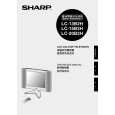
LC-20B2H/M
ADJUSTING PROCEDURE OF EACH SECTION
The best adjustment is made before shipping. If any position deviation is found or after part replace is performed, adjust as follows.
1. Preparation for Adjustments
(1)Use the exclusive-use AC adapter or stable DC power supply. AC adapter: UADP-0219CEZZ DC power supply: 13 ± 0.5V 3.5A
[1] Adjustment Procedure
1-1. Adjusting the checker Turning on the power (initialization) ) Setting the model and size in inches ) Transferring the model-specified data to the E2PROM (I2C) ) Calling the adjustment process mode ) Starting the adjustment (+B) 1-2. Adjusting the finish process Reassembling the set ) Turning on the power ) Calling the adjustment process mode (using the remote controller) ) Adjusting the counter bias, TV contrast and white balance
[2] Calling the MAIN adjustment process mode
There are the following three ways to choose from. � Turn on the power and press the "ADJUST PROCESS" key on the remote controller. � Set KEY 4 and KEY 5, pins (81) and (82), respectively, on the microprocessor to the "L" level. Now turn on the power. � For servicing, hold down the INPUT SELECT and MENU keys at once, and turn on the POWER switch. (Make sure the process mode "K" appears at the top left of the screen.) Then press the CH DOWN and VOL DOWN keys at once. (Make sure the adjustment process mode screen shows up.) To quit this mode, turn off the power. (Or turn off the POWER switch or use the remote controller�s OFF key.)
[3] Using the keys for the adjustment process
Selecting a reception channel � Using the CH UP/DOWN key, turn up and down reception (broadcasting) channels. Just click on the key, and channels are selected on by one. Hold down the key, and the next receivable channel is searched up and down. � Adjustment items Adjust each of the items by using the MENU SELECT, CURSOR UP/DOWN, CH UP/DOWN and VOL UP/ DOWN keys (on the set or on the remote controller). � Select an adjustment item using the CURSOR UP/DOWN key. � An adjustment item is toggled on and off by activating the MENU SELECT key (next item). Let�s suppose that the item at the bottom of a page is now selected. When the MENU SELECT key is activated here, the item at the top of the next page will be selected.
[4] Initialization
4-1. Set pins (81) and (82) of IC2001 (microprocessor) to GND. Turn on the power. 4-2. Select a model number ( C2H, B2H ). 4-3. Select a size in inches ( 10, 13, 15, 20 ).
[5] Adjustment
5-1. +B adjustment (R3760 Variable resistor) 1) Receive the color bar signal. 2) Adjust the voltage at SC3403 (pin (38)) to 5.00± 0.02 V. Note: The 5.0 V level is used as reference for all the line voltages. Make this adjustment as precisely as possible. 5-2. Counter bias adjustment: COM BIAS on page 2 Adjust the "COM BIAS" setting until the contrast gets optimum (the black portion blackest). For Model LC-13B2H,
12
|
|
|
> |
|