|
There are currently no product reviews.
 ;
Manuals were delivered promptly and were correct as advertised. No issues with the download link which was provided promptly after everything was processed. Very pleasant experience
;
Paid for service manual & got the download fast - worth a visit if you need a service manual
;
It's the manual, I am searching for. Now I am able to repair my Braun A501.
 ;
Great service manual. Unfortunately on page no. 41 there are some details which i can't read.
;
Wonderful service... doubt that I could have made the repairs to my turntable without this service manual. Great help!
Well worth the price paid!
LC-20B5E
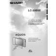
14. Remove the two lock screws from the inverter PWB, and detach the inverter PWB. 15. Remove the five lock screws from the main PWB, and undo the claws a and b. Detach the main PWB by lifting the area around the claws and pulling the PWB out. 16. Remove the one lock screw from the card frame cover over, and detach the card frame cover. 17. Remove the two lock screws from the 21-pin terminal. 18. Remove the four lock screws from the analog PWB, and undo the claws c and d. Detach the chassis frame (right) from the analog PWB by pulling out the terminals. In the same way, undo the claws e and f, and detach the chassis frame (left) from the analog PWB by pulling out the terminals. Note: When detaching the main PWB and analog PWB, be careful not to break the PWB-fixing claws. 19. Remove the one lock screw from the card LED PWB, and detach the card LED PWB.
18
15
Main PWB
15
16
Chassis Frame (L) a Analog PWB e
17 14
Card Frame Cover
b
c d
19
f
Chassis Frame (R)
Card LED PWB
Inverter PWB
10
|