|
There are currently no product reviews.
 ;
Everything okay, thanks a lot. It was a pleasure for me to make a deal with you.
;
A deal without problems, very fast and the manual is a good quality. Sorry for the my english.
;
Superb service and excellent quality of the document received
;
no problems with the purchase of a circuit diagram
;
Scan are good quality and overall just what i was looking for. Thanks!
LC-26GD6U
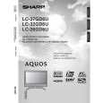
REMOVING OF MAJOR PARTS
� Display
1. 2. 3. 4. 5. 6. 7. Remove the 4 lock screws from the stand. Detach the left, right and bottom terminal covers. Remove the 2 lock screws each from the bracket covers. Remove the 4 lock screws from the speaker. Remove the 15 lock screws from the cabinet. Remove the 4 lock screws from the center angle. Take out the operation PWB.
Terminal Cover (right) 5 Cabinet A 2 5
7-1. Remove the 2 lock screws from the top cover. 7-2. Remove the 2 lock screws from the operation PWB. 8. 9. Remove the lock screw and detach the frame cover. Remove the 5 lock screws from the frame.
Stand Bracket Cover 2 3 4 1 3 Bracket Cover Terminal Cover (left) 2
10. Disconnect all the connectors from the PWBs.
6 Center Angle
7-1
9 9
P151
7-2
P2002 P7706 P5706 P1902 P5251 P3802 P1901 P1900 SC7200 P7200 P3700 P9001
8
Frame Cover
10
SC4601 P2021 P2003 P5102
P5002
SC3200 P5705 P5701 P3802 P7220 P1802 P1502
P1105 P5704
10
P3801 SC7201 P5003 P1501 P401 P501
P8901 P9301 P8801 P9751
P1803 P1804
10
14
|