|
There are currently no product reviews.
 ;
Very good scanning quality. All schematics are very legible. Worth every cent !
;
Excellent quality, very quick download turnaround, will definately use again.
 ;
This is a awesome quality scan of the original Service Manual for Technics 8099.
Contains the circuit diagram, PCB layout, adjust/tune instructions as well.
Since this is my first buy here, i'm really glad! This site do works as intended/described, it's definitely not scam!
Мои рекомендации! Все мануалы настоящие!
;
Good Quality of the File.
You get the normal manual is incudet.
;
Very nice and real Service Manual, I didn't thought it actually exist in the real world at all.
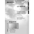
LC-30HV4E
7. Remove the system/control terminal retaining: 7-1. Remove the four hex head screws securing the terminals of the system and control cables (white). 7-2. Remove the two screws securing the terminal of the system cable (gray). 7-3. Remove the two rear chassis retaining screws. 8. Remove the PC I/F and SR units: 8-1. Remove the four PC I/F top shield retaining screws and remove the shield. 8-2. Remove the six PC I/F unit retaining screws and remove the unit. 8-3. Remove the two PC I/F bottom shield retaining screws and remove the angle. 8-4. Remove the two SR unit retaining screws and remove the SR unit. 9. Remove the 8 rear cabinet retaining screws and remove the rear chassis. ( 9 : XBPSN30P06000, 9 : XEBSF30P08000) 10. Remove the three power supply board retaining screws and remove the power supply board.
8-1
8-2 PC I/F unit shield
Rear chassis 9-2
8-3 PC I/F unit
9-1
PC I/F unit angle
SR unit 8-4
7-1 7-2 7-3
10
Power unit
14
|