|
|
|
Categories
|
|
Information
|
|
Featured Product
|
|
|
 |
|
|
There are currently no product reviews.
 ;
This is a high quality manual with clear schematic and components layout diagrams ; with service procedure included.
 ;
This service manual for the Kenwood KT-990D was reproduced really well ,is very legible and manual is complete.Combined with the low price paid,in the future,I will be checking Owner-Manuals.com any time I need a manual.
;
When I purchased this manual I had my doubts regarding the quality as the price was so reasonable as compared to other outlets.
The manual itself is of high standard the print is very clear as are the diagrams. Obviously with the diagrams one has to zoom in otherwise it is to small to be able to read.
Overall I am very pleased with the company who delivered as they said and with the manual they supplied.
I occasionally require a manual and now having registered with this company I shall order from them in the future.
;
I was at first dubious about payiong for downloaded manuals but having done so, I was extremely impressed with quality of the two manual I ordered, well worth the small price I paid.
I would highly recommend these to my friends.
;
reasonable price for the schematic - the service is perfect, all as expected and pointed by instructions - good scan of the original plans - thank you!
LC-26GA5U LC-32GA5U
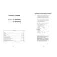
11. Remove the two lock screws from the LCD control PWB, and detach the LCD control PWB and heat sink. 12. Remove the six lock screws from the power PWB, and detach the power PWB. 13. Remove the four lock screws from the chassis frame (S), and detach the chassis frame (S). 14. Remove the AV PWB. 14-1. Remove the six lock screws from the AV unit, and detach the AV unit. 14-2. Remove the four lock screws from the chassis frame (L), and detach the chassis frame (L) 15. Remove the four lock screws from the inverter PWB, and detach the inverter PWB. (only for LC-26GA5U) 15. Remove the four lock screws from the inverter-1 PWB, and detach the inverter-1 PWB. (only for LC-32GA5U) 16. Remove the four lock screws from the inverter-2 PWB, and detach the inverter-2 PWB. (only for LC-32GA5U) 17. Remove the hree lock screws from the inverter-GND PWB, and detach the inverter-GND PWB. (only for LC-26GA5U) 17. Remove the six lock screws from the inverter-GND PWB, and detach the inverter-GND PWB. (only for LC-32GA5U) 18. Remove the four lock screws from the reinforcement angle (bottom), and detach the reinforcement angle (bottom). (only for LC-26GA5U) 19. Remove the two lock screws from the LCD panel unit, and detach the LCD panel unit. (only for LC-26GA5U) 19. Remove the one lock screw from the LCD panel unit, and detach the LCD panel unit. (only for LC-32GA5U)
11 LCD CONTROL PWB
LC-26GA5U LC-32GA5U
17 17
LC-32GA5U LC-26GA5U
15 15
LC-32GA5U
19 Heat Sink
LC-26GA5U
19
16
Chassis Frame (L) 14-2
Chassis Frame (S)
POWER PWB
12 18 13 14-1 AV PWB 14-1 13 18
LC-26GA5U
Reinforcement Angle (Bottom)
17
|
|
|
> |
|