|
|
|
Categories
|
|
Information
|
|
Featured Product
|
|
|
 |
|
|
There are currently no product reviews.
 ;
Downloaded the Service manual OK of the Technics Piano and have now repaired it and its going fine. Excellant; thank you for the fine servce. A.M
 ;
This site is working fine! Did buy a manual for SX-EX25L and after a while I could download it and fix the problem. Nice and easy!
;
Complete manual as pdf-file in very good quality. Very helpful and fast availability.
;
Complete service manual in very good scanning quality with all schematic and PWB graphics as well as assembly & maintenance instructions. A slight drawback is that the rastering of the PWB graphics sometimes makes it a bit difficult to follow fine traces, but no showstopper.
;
Purchased the manual that I was looking for at a great price and could download it easily.. Great service experience and for future purchases I plan to use the site. Thank you very much
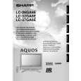
LC-26GA6E/LC-26BV6E LC-26GA5E LC-32GA6E/LC-32BV6E LC-32GA5E LC-37GA6E
7. Disconnect all the connectors from all the PWBs. 8. Remove the MAIN, HDMI and COMPONENT PWBs. 8-1. Remove the 3 lock screws 9 and the 2 lock screws 0. Detach the Chassis Frame. 8-2. Remove the 8 lock screws q and detach the MAIN PWB and HDMI/COMPONENT unit. 8-3. Remove the 4 lock screws w and detach the COMPONENT PWB from HDMI PWB. 9. Remove the 2 lock screws e and detach the R/C,LED PWB 10. Remove the 3 (LC-26GA6E) / 6 (LC-32GA6E) lock screws r and detach the INVERTER GND PWB. 11. LC-26GA6E : Remove the 4 lock screws t and detach the INVERTER PWB. LC-32GA6E : Remove the 8 lock screws t and detach the INVERTER-A and INVERTER-B PWBs. 12. Remove the 6 lock screws y and detach the LCD CONTROLLER PWB and Heat Sink. 13. Remove the 6 lock screws u and detach the POWER PWB. 14. Remove the 2 lock screws i and detach theSP BOX (L) and (R). (LC-26GA6E only)
CN7601 P2207 SC4651 SC4652 SC4601
SC2001 P2205 P2206 P7704
P2006
P7707
P7705
CN704 CN706
P2201 P1001 P1006 CN707
P1401
P1003 P1301
P1901 P2103 P2102
P1902 P2101
P4001
8
|
|
|
> |
|