|
There are currently no product reviews.
 ;
This manual is all I need to check and repair my equipment. Thank you....
;
This manual is all I need to check and repair my equipment. Thank you....
;
this manual make me repair my vintage radio with easily.
Thank you for your best service
sukpra
;
A good manual. Had everything i needed to make the repair.
;
This manual is a complete guide, including later additions. It has all the necessary information about the replacement items. The material quality is great to read.
LC-32GD1E LC-37GD1E
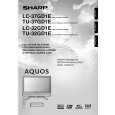
15. Remove the LCD CONT PWB mounting screw i to detach the LCD CONT PWB. 16. Remove the 6 POWER SUPPLY PWB mounting screws o to detach the POWER SUPPLY PWB. 17. Remove the 2 R/C LED PWB mounting screws p to detach the R/C LED PWB. 18. Remove the 4 INVERTER-A PWB mounting screws a to detach the INVERTER-A PWB. 19. Remove the 4 INVERTER-B PWB mounting screws s to detach the INVERTER-B PWB. 20. Remove the 4 INVERTER-A GND PWB mounting screws d to detach the INVERTER-A GND PWB. 21. Remove the 4 INVERTER-B GND PWB mounting screws f to detach the INVERTER-B GND PWB. 22. Remove the 4 MOTOR SP PWB mounting screws h to detach the MOTOR SP PWB. 23. Remove the 4 fan mounting screws g to detach the 2 fans. 24. Remove the 4 chassis mounting screws j, and remove the backlight chassis from cabinet A.
19 POWER SUPPLY PWB 27 FAN 25 27 FAN LCD CONT PWB 17 INVERTER-A GND PWB 18 INVERTER-A PWB 25 23
Backlight Chassis
INVERTER-B GND PWB
INVERTER-B PWB
22 20 R/C LED PWB 27 Remove the connector. 27 26 MOTOR SP PWB 24
15
|