|
|
|
Categories
|
|
Information
|
|
Featured Product
|
|
|
 |
|
|
There are currently no product reviews.
 ;
Complete service manual in excellent quality. I am very satisfied!
;
Complete service manual in excellent quality. I am very satisfied!
;
Excellent printing quality.
A complete and very usefull service manual with all details.
GREAT SERVICE AT VERY LOW PRICE!
A++
;
Excellent printing quality.
A complete and very usefull service manual with all details.
GREAT SERVICE AT VERY LOW PRICE!
A++
;
Excellent printing quality.
A complete and very usefull user manual with all details schematics.
GREAT MANUAL AT VERY LOW PRICE!
A++
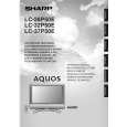
LC-26P50E LC-32P50E LC-37P50E
TROUBLE SHOOTING TABLE (Continued)
The backlight does not light.
Do all fluorescent lamps fail to light?
YES
NO
Check the fluorescent lamps that do not light. Replace thethe power. If the backlight still and turn on blown fuse(F703) or R1765 fails to light, check the area that has shorted out. In theoutput to CN702? Check that the 380 VDC POWER-UNIT: Is approximately RC701 operates properly. Is each control signal sent toCN1703 in CONNECTOR-CN1704 and the POWER UNIT? (VCC 2(14V), OFL1, INVáOSC) Replace the Z2501 (INV-CTL)(STRH2013).
YES
Replace the fluorescent lamps that do not light. Mainly check T7501, T7502 and their its peripheral circuits as well as Z7501 and peripherals.
In POWERfuse of the circuit for Check the UNIT: INVERTER-UNIT. Has the F703 2.0A in the POWER-UNIT blown? Is the value for R1765 1½ correct?
NO
YES
YES
In the INVERTER-UNIT: Is the power supplied between pins 1 and 2 of CONNECTOR-PN7501? (Pins 1 and 2 on the measuring point PN7501; 380 VDC)
YES
NO
YES
Check the connections of INV-PN7501 and POWER-CN702.
In the INVERTER-UNIT:(VCC 2(14V)_ signal sent to PN7503? Is each control 1Pin , OFL1_6Pin, INV-OSC_3Pin RETURN_2Pin)
YES
NO
NO
Check the OFL1 and INVáOSC-LINE of CONNECTOR-P4101 in the MAIN-UNIT and UR14V-LINE in the POWER-UNIT.
In the INVERTER-UNIT: Is the control signal of Z2501 (INV-CTL)(STR-H2013) output correctly? (PDRV1/V2(22)(20)Pin)
YES
NO
Check the photocoupler (PC 7501-22) and the output transformer (T7503-25). Also check the lamp connector connection.
45
|
|
|
> |
|