|
|
|
Categories
|
|
Information
|
|
Featured Product
|
|
|
 |
|
|
There are currently no product reviews.
 ;
Very good service Within one day i received a pdf of the users manual and electric circuits so I was able to measure the different voltages in the printed circuit and find out the fault Payment was also reliable and easy.Without the manual i could not have repaired.So thanks to "Search for a manual"
 ;
you are doing great job guys.....my father ask me to find out the schematics of Sony KV25R1D to sort out the problem ..(he was electrical technician, and excperianced with TV and simillar stuff). finally he found the cause and change all necessary parts....now he has got working old dog..and is very happy!!... thank you all.. NB..he also saved the repair cost.
;
Perfect. Received my manual within 24 hours. Clear scan of the manual I needed. No problem.
;
Item as described, very well detailed manual with complete schematics. I've received the download information shortly after payment, very good support.
;
Really good and well scanned. File is complete the full service manual for 5$
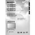
LC-32GD1E LC-37GD1E
15. Remove the LCD CONT PWB mounting screw i to detach the LCD CONT PWB. 16. Remove the 6 POWER SUPPLY PWB mounting screws o to detach the POWER SUPPLY PWB. 17. Remove the 2 R/C LED PWB mounting screws p to detach the R/C LED PWB. 18. Remove the 4 INVERTER-A PWB mounting screws a to detach the INVERTER-A PWB. 19. Remove the 4 INVERTER-B PWB mounting screws s to detach the INVERTER-B PWB. 20. Remove the 4 INVERTER-A GND PWB mounting screws d to detach the INVERTER-A GND PWB. 21. Remove the 4 INVERTER-B GND PWB mounting screws f to detach the INVERTER-B GND PWB. 22. Remove the 4 MOTOR SP PWB mounting screws h to detach the MOTOR SP PWB. 23. Remove the 4 fan mounting screws g to detach the 2 fans. 24. Remove the 4 chassis mounting screws j, and remove the backlight chassis from cabinet A.
19 POWER SUPPLY PWB 27 FAN 25 27 FAN LCD CONT PWB 17 INVERTER-A GND PWB 18 INVERTER-A PWB 25 23
Backlight Chassis
INVERTER-B GND PWB
INVERTER-B PWB
22 20 R/C LED PWB 27 Remove the connector. 27 26 MOTOR SP PWB 24
15
|
|
|
> |
|