|
There are currently no product reviews.
 ;
This manual was exactly what I needed. Detailed, useful and delivered as promised.
 ;
Great manual good quality really helped in the repair of my Toshiba, thanks
;
Print was clear and easy to read. Thank you Joe joeoldaudio
;
Very great deal. In a few minutes a have the manual, that I needed. Thanl you very much
;
Manual was complete. Received it quickly. No problems
LC-26P50E LC-32P50E LC-37P50E
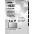
10.Unplug the FFC/FPC wires from SC4651, SC4652, and SC1202 - SC3701. 11.Unplug the connecting cables from these connectors: CN702, CN1701, CN1702, CN1703, CN1704, CN1705, P5700, P1201, and P3900. 12.Remove the 9 lock screws 9 and detach the Power Unit. 13.Remove the 5 lock screws 0 and detach the Main Unit. 14.Remove the 5 lock screws q and detach the Main Shield(Top) and Main Shield(Bottom) from Main Unit. 15.Remove the 2 lock screws w and detach the R/C, LED Unit. 16.Remove the 4 lock screws e and 2 lock screws r and detach the AV Unit. 17.Remove the 1 lock screw t and 2 lock screws y and detach the Chassis Frame and Tuneer Shiled from AV Unit.
SC3701 SC4651 SC4652 SC1202 P5700 P3900 CN1702 CN1704 CN702 CN1705 CN1703 CN1701 PN7523 PN7517
P1201
PN7622 PN7516
14 15
13 AV Unit 11
11
11
10 11
11 16
Main Shield(Top)
Main PWB Chassis Frame Tuner Shield Main Shield(Bottom)
R/C LED Unit 12 Power Unit 9
14
|