|
There are currently no product reviews.
 ;
Very quick and easy website to use and fast download of manual, quality of manual is excellent and will be pleased to use this service again in the future, thanks so much!
;
It is an very good and clear scanned service manual.
very recommended.
;
Easy to order the manual. Good quality and fast delivery.
;
The Service Manual for Sansui AU-9500 was very helpfull, in complete and in good printable condition.
Thanks.
;
Dear Sir,
Document is original service document of sharp. I had a problem with the door contacts. Fuses where blown. With the manual in a few minuts is was clear what the problem was.
Manual was of great help.
With kind regards,
Martie Verhoeven
The Netherlands.
4-2
LC6231/LC7181
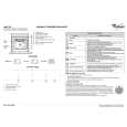
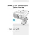
5. Remove the 6 screws �F� holding the top shield (Fig. 5). Then remove the 3 screws �G� and the 2 screws �H� (Fig. 6). Now the top shield can be removed. 2. Remove screw �K� and connectors �L� (Fig. 8). Nor the DRB (Drive Boards) can be removed.
DRB Board
F F F
F
F
F
CL 266450004_049.eps 240402
K
L
CL 266450004_052.eps 240402
Fig. 5
Fig. 8
H
H
3.
Remove screw �L� (Fig. 9). Now the bottom shield can be removed.
L
G
G
G
CL 266450004_050.eps 24402
Fig. 6 4.2 Panel removal and service position 1.
Bottom Shield
Remove screw �I� and connectors �J� (Fig. 7). Now the SSB (Small Signal Board) can be removed. The SSB is plugged onto the DRB (Drive Board).
DRB Board
Fig. 9
CL 266450004_053.eps 240402
J
J J
I
SSB Board
CL 266450004_051.eps 240402
Fig. 7
|