|
|
|
Categories
|
|
Information
|
|
Featured Product
|
|
|
 |
|
|
There are currently no product reviews.
 ;
This manual was the factory original. Excellent value and contained all the details I needed. Easy dowwnload provided the information when I needed it.
 ;
Impeccable, document très complet. Perfect, i get all i need. All schematic are correct. Thanks
;
The manual is of better quality compared to other. I found it less expensive and therefore it it is the best buy cost vs quality.
;
I bought the service-manual of the sony ICB-1020(an old transmitter-receiver) at "www.Owners-Manual.com", I found the service-manual for a fairly cheap price(in comparison with other sellers). I filled in some questions, payed the order with Ideal, and within 24 hours I had my service manual. I was very happy:In no time I had my service-manual and everything, but literally everything was noted down in the manual; the electronic scheme, the parts list, etcetera.
A very practical, reference-document.
;
This comprehesive service maual was greatly appreciated, as was the digital download.
3.3 REPLACEMENT OF CHIP COMPONENT 3.3.1 (1) (2) (3) (4) CAUTIONS Avoid heating for more than 3 seconds. Do not rub the electrodes and the resist parts of the pattern. When removing a chip part, melt the solder adequately. Do not reuse a chip part after removing it.
3.3.2 SOLDERING IRON (1) Use a high insulation soldering iron with a thin pointed end of it. (2) A 30w soldering iron is recommended for easily removing parts. 3.3.3 REPLACEMENT STEPS 1. How to remove Chip parts [Resistors, capacitors, etc.] (1) As shown in the figure, push the part with tweezers and alternately melt the solder at each end. 2. How to install Chip parts [Resistors, capacitors, etc.] (1) Apply solder to the pattern as indicated in the figure.
(2) Grasp the chip part with tweezers and place it on the solder. Then heat and melt the solder at both ends of the chip part. (2) Shift with tweezers and remove the chip part.
[Transistors, diodes, variable resistors, etc.] (1) Apply extra solder to each lead.
[Transistors, diodes, variable resistors, etc.] (1) Apply solder to the pattern as indicated in the figure. (2) Grasp the chip part with tweezers and place it on the solder. (3) First solder lead A as indicated in the figure.
SOLDER
SOLDER
(2) As shown in the figure, push the part with tweezers and alternately melt the solder at each lead. Shift and remove the chip part.
A B C
(4) Then solder leads B and C.
A B
Note : After removing the part, remove remaining solder from the pattern.
C
(No. YA035) 1-21
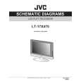
 $4.99 LT-17X475 JVC
Parts Catalog Parts Catalog only. It's available in PDF format. Useful, if Your equipment is broken and You need t…
|
|
|
> |
|