|
|
|
Categories
|
|
Information
|
|
Featured Product
|
|
|
 |
|
|
There are currently no product reviews.
 ;
As Always you can find here manuals even of difficult TV scheme which are scan in almost perfect way.clear and fast!!!!!
Great work thanks!
;
Incredibly clear!!!! Well done, complete and wonderful. It could not better than this!!!!
 ;
Thank You for fast delivery for the sheme.
Everything allright.
Thanks & best regards Franz
;
again you did a very good job. It was fast too. Photocopy are really readable and clear
;
Probably it never existed a 1081 official service manual from Commodore, it's look more like a NAPCEC service manual & diagrams compilation of the 1084 series and his variants, like the nap6523, 8cm505, 1084S, 1084P and obviously the 1081. It's more complete than other scans and the quality of the scans also are far superior. It has two circuit diagrams variants of the 1081, mono and stereo versions. It doesn't include a diagram for the Philips CM8500 or CM8501, they look like the 1081 but they are slightly different.
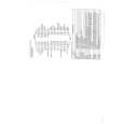
LZ-601
ADJUSTMENT
No. ITEM INPUT SETTINGS OUTPUT SETTINGS ALIGNMENT POINTS ALIGN FOR 1. After turning the unit on, warm it up for 15 minutes before proceeding to the adjustment. 2. Adjust S207 so that the voltage at IC201 pin 32 is 2.30V±0.1V DC. 3. 1) Turn the knob (BRIGHT) to the center position. (It is put to the center position at the moment the unit is turned Puts a video 4 BRIGHT signal for the inspection in VIDEO IN on.) Connect a DC voltmeter to IC201 (32P) S207 2) Adjust S207 so that the second grid from the right of the gray scale dims by about 20%. 3) Turn the knob (BRIGHT) to the MAX position and confirm that the three grids from the left of the gray scale are distinguishable.
Distinguish Distinguish Not distinguish
STANDARD
IC201 32pin (Bright) DC : 2.30V±0.1V 2) BRIGHT : CENTER
5 4 3 2 1
3) BRIGHT : MAX
5 4 3 2 1
4) BRIGHT : MIN
5 4 3 2 1
4) Turn the knob (BRIGHT) to the MIN position and confirm that the three grids on the right of the gray scale are distinguishable. 1. After turning the unit on, warm it up for 15 minutes before proceeding to the adjustment. Puts a video 5 WHITE BALANCE signal for the inspection in VIDEO IN 2. Turn the knob (BRIGHT) to the Connect a DC voltmeter to IC201(27P or 28P) S204 S205 center position. (It is put to the center position at the moment the unit is turned on.) 3. R adjustment: Adjust S204 so that the background is reddish. 4. B adjustment: Adjust S205 so that the picture is gray.
Not distinguish
IC201 27pin SVR204 DC : 1.75V±0.1V IC201 28pin SVR205 DC : 1.80V±0.1V
3
|
|
|
> |
|