|
|
|
Categories
|
|
Information
|
|
Featured Product
|
|
|
 |
|
|
There are currently no product reviews.
 ;
Great value, good scan, just as expected, everything that you need.
;
Good scan, great price, but almost the same with the SV260 service manual.
;
This PDF is very comprehensive. It includes drawings, parts lists, schematics, pictures, PCB drawings, mechanical layouts, etc. for all three stackable equipment. The scans are good too. Easy to read and no smudges or black lines. I have no complaints. I will make this site my first stop for finding my service manuals.
 ;
This service manual includes drawings, schematics, exploded views, parts list, operating details, and more. Very good scans, very readable. The only thing that made it a 4 star rating was on approximately 4 scans only half of the page was scanned then the other half. I would have preferred the pages to be whole scans.
;
Good manual contains all it takes to update, repair,these types of mixers.Thanks.
5. Special Circuit Descriptions
5-1 CD
5-1-1 RF Amp (KA9220) : WIC01
58K B A D Photo Detector C
65
PD1 PD2 RF I-V AMP(1) 58K
R1 10K
RF SUMMING V1 AMP
RFO
RF I-V Amp(1) and RF I-V Amp(2) are converted to voltage via internal resistance of 58k½ from the current of PD1(A+C) and PD2(B+D): This voltage is added to RF summing amplifier. The signal (A+B+C+D) is applied to RFO (No. 66 terminal). RF output voltage is calculated as follows :
74 66
R3 10K R2 V2
VRF = -R3 x (iPD1 + iPD2) VRF = -R3 x (V1/R1 + V2/R2) VRF = -R3 x ( VRF = R3 10K V1 10K
66
RF I-V AMP(2)
73
RF
+
V2 10K
)
x (V1 + V2)
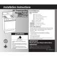
5-1-2 FOCUS ERROR Amp(KA9220) : WIC01
R2 174K C1 25P R1 V1 32K -(B+D) -(A+C) 32K C2 25P 164K FOCUS ERROR AMP FE
59
FOCUS ERROR Amp is the circuit which amplifies the difference between RF I-V Amp(1) output (A+C) and RF I-V Amp(2) output(B+D). These two signals are supplied to (-) and (+) input terminals of FOCUS ERROR Amp. The FOCUS ERROR signal resulting from this difference voltage is applied to FE (Terminal No.57). The FE output voltage of this low frequency component varies according to {(A+C) - (B+D)}. VFE is calculated as follows :
VFE = (R2/R1) x (V2-V1) = 5.4(V2-V1)
This FOCUS ERROR voltage is sent to FOCUS SERVO .
5-1-3 FOCUS SERVO SYSTEM (KA9220) : WIC01
When FS3 is ON, high frequency gain decreases (time constant set by pin17, pin19, and capacitor connected to internal resistance). The capacitor between pin 18 and GND sets the time constant to pass the low frequency operated in PLAY mode.
3.6K
60K FE1 20K 0.0022
FZC 20K 48K FS4 130K FS2 470K 46K 580K FS3 FSW 0.1UF 40K FS1 PFSET FSCH 4.7UF 10K 50K 92K PHASE COMPENSATION 40K 5.5U 11U
58 60
0.1UF
FE2 470K
48
FSEO FOCUS COIL FCE
120K
DFCT FDFCT
47 20 ISET
62
0.1UF
HFGD EFR
61
180K
21
VREG
27
6
3
The maximum frequency of focus phase compensation is inversely proportional to the resistance connected to pin 7. Focus search peak is about 1.1 Vp-p, and is inversely proportional to the resistance connected to pins 22,23 (if this resistance changes, the peak of track jump and sled kick change). The inversion input of FZC comparator is set to 5.7% of the difference between Vcc and VC(pin69) {{5.7% x (Vcc-Vc)}. Note : If the resistance connected to pin7 changes, the phase compensation peak of focus, tracking, sled servo changes. At the same time, 'op-amp' dynamic range and offset voltage also change. Samsung Electronics 5-1
|
|
|
> |
|