|
|
|
Categories
|
|
Information
|
|
Featured Product
|
|
|
 |
|
|
There are currently no product reviews.
 ;
Thank You for fast delivery for the sheme.
Everything allright.
Thanks & best regards Franz
 ;
again you did a very good job. It was fast too. Photocopy are really readable and clear
;
Probably it never existed a 1081 official service manual from Commodore, it's look more like a NAPCEC service manual & diagrams compilation of the 1084 series and his variants, like the nap6523, 8cm505, 1084S, 1084P and obviously the 1081. It's more complete than other scans and the quality of the scans also are far superior. It has two circuit diagrams variants of the 1081, mono and stereo versions. It doesn't include a diagram for the Philips CM8500 or CM8501, they look like the 1081 but they are slightly different.
;
Rapid, clear well done as all the scheme I downloaded from this site. Great job very functional and very useful
;
Great copy of the manual, has all information required for servicing,
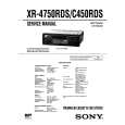
QL21,QL74:LC74781 Q601:YSS912
SDOB0 SDOB3
Microprocessor Coefficient /
SDOB Interface
/CSB
SDBCK1 Control Registers /SDBCK0 SDWCK1
SCK SI
24 * 16 Sub DSP
SDBCK0 SDWCK0
OVFB RAMA0 16 RAMOEN RAMWEN RAMCEN
SDIB Interface SDIBSEL
SDOB1 LS, RS
RAMD0 7
SDIB3 SDIB2 SDIB1 SDIB0 SDOA2 SDOA1 SDOA0
MUTE Operating clock Interface
C, LFE
SDOACKSEL SDIBCKSEL SDOBCKSEL
SDOB2 SDIA1
L, R
SDOA Interface
OPORT0 7 SCK SI SO /CS
24 * 24 Main DSP AC-3/Pro Logic/DTS
Interface Program RAM
SURENC STREAM 0 7
Decoder
NONPCM
CPO
Input Buffer
IPORT0 7
XO XI
Control signals
SDIA Interface SDIASEL
KARAOKE ExternalRAM
CRC
No. 1 2 3 4 5 6 7 8 9 10 11 12 13 14 15 16 17 18 19 20 21 22 23 24 25 26 27 28 29 30 31 32 33 34 35 36 37 38 39 40 41 42 43 44 45 46 47 48 49 50
NAME I/O FUNCTION VDD1 - +5V power supply (for I/Os) RAMCEN O External SRAM Interface /CE RAMA16 O External SRAM Interface address 16 RAMA15 O External SRAM Interface address 15 SDIB0 I+ PCM input 0 to Sub DSP SDIB1 I+ PCM input 1 to Sub DSP SDIB2 I+ PCM input 2 to Sub DSP XI I Crystal oscillator connection or input external clock (12.288 MHz) XO o Crystal oscillator connection VSS - Ground AVDD - +3.3V power supply (for PLL circuit) SDIB3 I+ PCM input 3 to Sub DSP TEST Test terminal (to be open in normal use) TEST Test terminal (to be open in normal use) OVFB O Detection of overflow at Sub DSP DTSDATA O DTS data detection (Refer to "Status Register".) AC3DATA O AC-3 data detection (Refer to "Status Register" .) SDOB3 O PCM output from Sub DSP CPO A Output terminal for PLL, to be connected to ground through the external analog filter circuit. (Refer to "External Circuit for PLL" .) AVSS - Ground (for PLL circuit) VDD2 - +3.3V power supply (for core logic) SDOA2 o PCM output from Main DSP (C, LFE) SDOA1 O PCM output from Main DSP (LS, RS) SDOA0 O PCM output from Main DSP (L, R) RAMA14 O External SRAM Interface address 14 RAMA13 O External SRAM Interface address 13 RAMA12 O External SRAM Interface address 12 RAMA11 O External SRAM Interface address 11 RAMA10 O External SRAM Interface address 10 VSS - Ground VDD1 - +5V power supply (for I/Os) OPORT0 O Output port for general purpose. (Refer to " OPORT Register") OPORT1 O Output port for general purpose. (Refer to " OPORT Register") OPORT2 O Output port for general purpose. (Refer to " OPORT Register") OPORT3 O Output port for general purpose. (Refer to " OPORT Register") OPORT4 O Output port for general purpose. (Refer to " OPORT Register") OPORT5 O Output port for general purpose. (Refer to " OPORT Register") OPORT6 O Output port for general purpose. (Refer to " OPORT Register") OPORT7 O Output port for general purpose. (Refer to " OPORT Register") VSS - Ground VDD2 - +3.3V power supply (for core logic) RAMA9 O External SRAM interface address 9 RAMA8 O External SRAM interface address 8 RAMA7 O External SRAM interface address 7 SDOB2 O PCM output from Sub DSP SDOB1 O PCM output from Sub DSP SDOB0 O PCM output from Sub DSP SDBCK1 I+ Bit clock input for SDOA, SDIB, SDOB. (Refer to " SDOA, SDIB, SDOB Register") SDWCK1 I+ Word clock input for SDOA, SDIB, SDOB. (Refer to " SDOA, SDIB, SDOB Register") VSS - Ground
CRC (30MHz) Data RAM AC3DATA ERAMUSE Delay RAM DTSDATA PLL
SDIA0
No. 51 52 53 54 55 56 57 58 59 60 61 62 63 64 65 66 67 68 69 70 71 72 73 74 75 76 77 78 79 80 81 82 83 84 85 86 87 88 89 90 91 92 93 94 95 96 97 98 99 100
NAME VDD2 NONPCM CRC MUTE KARAOKE SURENC /SDBCK0 RAMA6 RAMA5 VSS RAMA4 /lC TEST RAMA3 /CSB /CS SO SI SCK RAMA2 VDD1 RAMD0 RAMD1 RAMD2 RAMD3 RAMD4 RAMD5 RAMD6 RAMD7 VSS VDD2 SDWCK0 SDBCK0 SDIA0 SDIA1 RAMA1 RAMA0 RAMWEN RAMOEN VSS VDD2 IPORT7 IPORT6 IPORT5 IPORT4 IPORT3 IPORT2 IPORT1 IPORT0 VSS Note )
I/O O O O O O O O O O Is O Is+ Is Ot Is Is O I+/O I+/O I+/O I+/O I+/O I+/O I+/O I+/O I I I I O O O O I+ I+ I+ I+ I+ I+ I+ I+
FUNCTION +3.3V power supply (for core logic) Detection of non PCM data. (Refer to " Status Register") Detection of AC-3 CRC error. (Refer to " Status Register") Detection of auto-mute. (Refer to " Status Register") Detection of AC-3 karaoke data. (Refer to " Status Register") Detection of AC-3 2/0 mode Dolby surround encoded input (Refer to " Status Register") Inverted SDBCKO clock output (refer to " Block diagram") External SRAM Interface address 6 External SRAM Interface address 5 Ground External SRAM Interface address 4 Initial clear Test terminal (to be open in normal use) External SRAM Interface address 3 Sub DSP Chip select Microprocessor interface Chip select Microprocessor interface Serial data output Microprocessor interface/Sub DSP Serial data input Microprocessor interface/Sub DSP clock input External SRAM Interface address 2 +5V power supply (for I/Os) External SRAM Interface data (STREAM 0 output when External SRAM is not in use) External SRAM Interface data (STREAM 1 output when External SRAM is not in use) External SRAM Interface data (STREAM 2 output when External SRAM is not in use) External SRAM Interface data (STREAM 3 output when External SRAM is not in use) External SRAM Interface data (STREAM 4 output when External SRAM is not in use) External SRAM Interface data (STREAM 5 output when External SRAM is not in use) External SRAM Interface data (STREAM 6 output when External SRAM is not in use) External SRAM Interface data (STREAM 7 output when External SRAM is not in use) Ground +3.3V power supply (for core logic) Word clock input for SDIA, SDOA, SDIB, SDOB (Refer to " SDIA, SDOA, SDIB, SDOB Register") Bit clock input for SDIA SDOA SDIB SDOB (Refer to " SDIA, SDOA, SDIB, SDOB Register") AC-3/DTS bitstream (or PCM) data input for Main DSP (Refer to " SDIA Register") AC-3/DTS bitstream (or PCM) data input for Main DSP (Refer to " SDIA Register") External SRAM Interface address 1 External SRAM Interface address 0 External SRAM Interface /WE External SRAM Interface /OE Ground +3.3V power supply (for core logic) Input port for general purpose (Refer to " IPORT Register") Input port for general purpose (Refer to " IPORT Register") Input port for general purpose (Refer to " IPORT Register") Input port for general purpose (Refer to " IPORT Register") Input port for general purpose (Refer to " IPORT Register") Input port for general purpose (Refer to " IPORT Register") Input port for general purpose (Refer to " IPORT Register") Input port for general purpose (Refer to " IPORT Register") Ground Schmidt trigger input terminal Input terminal with a pull-up resistor Digital output terminal Tri-state digital output terminal Analog terminal
43
Is : I+ : O: Ot : A:
44
|
|
|
> |
|