|
|
|
Categories
|
|
Information
|
|
Featured Product
|
|
|
 |
|
|
There are currently no product reviews.
 ;
Superb rendition. Drawings (schematics) complete and unabridged. I do a great deal of vintage audio restoration. Documentation is essential for successful repairs. I have found sources over the years that offer good documentation, but rarely all that is necessary. Owner's Manuals has filled that void with complete and legible documentation. They have narrowed my "favorites" to a more manageable collection. This Denon manual in particular contained the latest revisions level, and offered alterations favorable to updating the item. The Illustrated Parts Breakdown (IPB) was well enough detailed to simplify part symbols and physical locations. You will not be disappointed!
;
Clear and concise. Saved me a lot of time and money.
;
Superb manual. Exactly what I ordered and made available in a very timely manner.
 ;
very fast detailed and accurate hope to do business again
;
This was precisely what I was looking for. Complete and good quality!
3-2
3-2
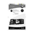
Dismantling of the Front Panel assembly
1) Loosen 4 screws C in figure 7 to remove the ETF8 Module. 2) Insert a strong string into the slot between the Jog knob (pos 136) and Cover control (pos 137), looped it until it engage into both the U-slot of the Jog knob and pulled it out as shown in figure 6. 3) Loosen 4 screws D to remove the Display Board assembly.
Dismantling of the Bottom assembly
1) Loosen 1 screw H as shown in figure 9 to remove the Combi board assembly. 2) Loosen 1 screw J and uncatch Shield Transformer (pos 269) from the Bottom plate (pos 265) as shown in figure 11 to remove it. 3) Loosen 4 screws K mounting the Mains Transformer (pos 5001) to remove the Mains Board & Transformer assembly. 4) Loosen 4 screws L to remove the Fan (pos 267). Note: During Fan replacement care should be taken to ensure that the following are correct: - fan blades direction - fan wire position
figure 9
figure 6
figure 7
Dismantling of Rear Panel
1) Loosen 3 screws E and 2 catches C3 to remove the Tuner Board assembly. Note: Tuner Board assembly can also be remove together with the Panel Rear. 2) Loosen 1 screw F and the 2 catches C4 to free the Mains socket board from the Panel Rear (pos 256). 3) Loosen 5 screws G and 2 catches C5 to remove the Panel Rear (pos 256) by sliding it out towards the rear.
figure 10
Twist screw driver
figure 11
figure 8
 $4.99 MC77 PHILIPS
Owner's Manual Complete owner's manual in digital format. The manual will be available for download as PDF file aft…
|
|
|
> |
|