|
|
|
Categories
|
|
Information
|
|
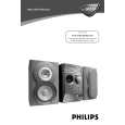
Featured Product
|
|
|
 |
|
|
There are currently no product reviews.
 ;
very good manual, with detail and clarity in esquematic diagrams and waveforms .
 ;
Very quality copy of original service manual, which contains the circuit diagrams, PCB and lists of components, well as recommendation for calibration procedures of device, also everything else, that need for repair, tuning and use this oscilloscope.
All presented copies have high-resolution, so you can view all in detail.
This manual will very useful for simple owners and for repairers.
I recommend these manual, because myself is owner of Philips PM3216 and I need sometimes servicing these oscilloscope (principally calibrating).
Also, these document is an example of excellent design of technical documentation.
;
Excellent printing quality.
A complete and very usefull service manual with all details.
GREAT SERVICE AT VERY LOW PRICE!
A+++++++++++++++++++++++++
;
manual excelente completo , diagramas y esquemas bien presentados y buena calidad de imagen.
;
muy buen manual completo de buena calidad de impresion preciso y detallado , muy útil para la reparación.
Service Hints
4. MEASURE THE LASER CURRENT
CD DRIVE � LASER CURRENT MEASUREMENT
The laser current can be measured as a voltage drop on resistor 3820. Typical value 170 - 190mV for CD-DA respectively 200 - 220mV for CD-RW.
3818 47n 47R
10-3
6. MEASURE THE OFFSETS OF THE CD10
SIGNAL PROCESSOR � OFFSET MEASUREMENT
Each ADC input of the CD10 may have an offset too. Also this offset leads (together with the offsets of the CD Drive) to poor playability of some CDs (skipping tracks). Start the Service Test Program - section �Focus Test� using a CD-RW disc. Use a DC Millivoltmeter for measurement. The offsets can be measured on capacitors near the signal processor. See drawing below.
Laser power control
2876 U >250mV ->Laser damaged !
1R 47u
3820 2878 +5V 100n 4R7 3822
+5V_HF 470n 3821 2877
2841
3817
3819
47R
100n
The value should read 0mV±10mV.
4,6V 3 0,17V
3,9V 3,3V 7879 BC807-40 47R
10K 7811-A 8 LM358D 3823 1 1K 3V 4
CD Board side A view
2 2879 2880
LASER DIODE
2V 2869
0,17V 1n 33p
5. MEASURE THE OFFSETS OF THE CD-DRIVE
CD DRIVE � OFFSET MEASUREMENT
Each photodiode of the CD-drive may have an offset. This offset has to be compensated by the signal processor. A high offset of the CD-drive leads to poor playability of some CDs (skipping tracks). Start the Service Test Program - section �Focus Test� without a CD. Focus sensitivity = CD-RW. Use a DC Millivoltmeter for measurement. The offsets can be measured direct on the connector. See drawing below.
B VREF A C D F E
Signal Processor
The values from diode A-D should read 0±10mV. Diodes E and F are less critical.
3
4
5
CD Drive Sanyo DA12T3
VREF VCC E
E B C D F A
If one of the offsets is higher than ±10mV the signal processor has to be replaced.
1800
16 VrefCD10 15 14 13 12 11 10 9 8
E D A B C F
If none of the measured offsets is higher than ±10mV replace the part with the higher value.
+5V_HF E D A B C F
D A B C F GND
If one of the offsets is higher than ±10mV the CD drive has to be replaced.
|
|
|
> |
|