|
|
|
Categories
|
|
Information
|
|
Featured Product
|
|
|
 |
|
|
There are currently no product reviews.
 ;
Thought I would never find a copy of the Technics SX-EN2 Service Manual until I found Owner-Manuals.com. Price was very fair and I received the download promptly. While a photocopy, it is quite readable and includes all the pertinent information and diagrams. Thank you Owner-Manuals!
 ;
I really like this manual and it's reliable.I found and bought easly.thank you.
;
Thank you very much. the Instruction corresponds to my expectations. Sent it in time. I don't regret that paid money.
;
Good quality. Quick service. I recommend to everyone.
;
Very good quality scan of the document. I am very pleased with what I got.
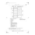
EXPLODED VIEW (BODY, MOTOR HOUSING, AND
C-46 C-59 C-35
MOTOR)� C BLOCK
AGITATOR ASSEMBLY REMOVAL/INSTALLATION
Removal
The brushes are replaceable separately. When the brushes need replacing, the agitator assembly will have to be removed. 1. Remove the lower plate as outlined in the LOWER PLATE REMOVAL/ INSTALLATION section. 2. Carefully lift up on the agitator assembly until it clears both sides of the nozzle housing, (Fig. 3).
C-41 C-36 C-39 C-38
C-45 C-44
C-7
C-37
C-5 C-43
3. Remove the belt from the motor shaft by sliding it off between the end of the shaft and the nozzle housing, (Fig. 4).
(Fig. 3)
Tabs
C-66
Installation
C-19 C-41
1. Place the belt around the motor shaft, (Fig. 4). 2. Start the agitator assembly back into the nozzle housing by placing the side opposite the belt partially into the slot. This will hold the agitator in place and leave both hands free to place enough tension on the belt to allow that side of the agitator to return to the nozzle housing slot.
C-40 C-6 C-12 C-2
C-53 C-8 C-50 C-54 C-52 C-55 C-51 C-10 C-54 C-47 C-4 C-3 C-1 C-60 C-11
3. Place the belt around the agitator pulley on the agitator assembly. NOTE: There is a place for the belt to fit on one end of the agitator assembly only. This is the agitator pulley.
(Fig. 4)
C-9
C-22
C-21
4. Use both hands to pull the belt tight, (Fig. 5), and slide the agitator assembly firmly into the slots on each end of the nozzle housing.
A VC GAU GE
FULL
5 Rotate the agitator assembly by hand to insure nothing rubs and to check for correct assembly.
C-42 C-65 C-64
6. Replace the lower plate as outlined in the LOWER PLATE REMOVAL/INSTALLATION section.
(Fig. 5)
C-18 C-17 C-15 C-16 C-20 C-33 C-34
BELT REPLACEMENT
Removal
C-18 C-24 C-25 C-48 C-49 C-17
1. Follow all of the removal instructions outlined in the AGITATOR ASSEMBLY REMOVAL/INSTALLATION section.
C-15 C-27
Installation
2. Place the new belt around the motor shaft and follow the installation instructions in the AGITATOR ASSEMBLY REMOVAL/INSTALLATION section.
C-14
C-61
C-57 C-26 C-23 C-31 C-62
C-58
C-28 C-63 C-62 C-56 C-30 C-32
C-13
-8-
- 13 -
|
|
|
> |
|