|
|
|
Categories
|
|
Information
|
|
Featured Product
|
|
|
 |
|
|
There are currently no product reviews.
 ;
This is a high quality manual with clear schematic and components layout diagrams ; with service procedure included.
 ;
This service manual for the Kenwood KT-990D was reproduced really well ,is very legible and manual is complete.Combined with the low price paid,in the future,I will be checking Owner-Manuals.com any time I need a manual.
;
When I purchased this manual I had my doubts regarding the quality as the price was so reasonable as compared to other outlets.
The manual itself is of high standard the print is very clear as are the diagrams. Obviously with the diagrams one has to zoom in otherwise it is to small to be able to read.
Overall I am very pleased with the company who delivered as they said and with the manual they supplied.
I occasionally require a manual and now having registered with this company I shall order from them in the future.
;
I was at first dubious about payiong for downloaded manuals but having done so, I was extremely impressed with quality of the two manual I ordered, well worth the small price I paid.
I would highly recommend these to my friends.
;
reasonable price for the schematic - the service is perfect, all as expected and pointed by instructions - good scan of the original plans - thank you!
NOZZLE HOUSING REMOVAL/INSTALLATION
REMOVAL
1. Turn the vacuum cleaner over exposing the underside. Release the nozzle housing by removing the five (5) screws that secure the nozzle housing, (Fig 4). 2. After removing screws turn the vacuum cleaner back over and remove hoses from top cover, (Fig 4). 3. Remove the screw holding the Bare Floor/Carpet selector switch and remove the switch. 4. Remove the nozzle housing by grasping the snap at the back just behind the agitator housing, lift up, pivoting it toward the agitator until it releases from the slots in front. Remove any residue that may exist in the belt area.
Snap
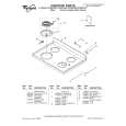
EXPLODED VIEW (MOTOR HOUSING, MOTOR, AND BODY)...
BLOCK C
Hose
C-41
Bare Floor Selector Switch C-3 Hose C-5
C-2
C-4
INSTALLATION
Nozzle Housing Cover
C-8
(Fig. 1) 4)
1. Hook the front of the nozzle housing into the slots on the front of the nozzle housing. Press the lower plate down into place. The housing will snap into place. 2. Replace the five (5) lower plate mounting screws. 3. Replace the Bare Floor selector switch and screw.
C-9
C-6
C-7
C-1
AGITATOR ASSEMBLY REMOVAL/INSTALLATION
Note: Before removal make sure the Bare Floor/Carpet Selector is in bare floor mode.
Gear Box Screw C-12 Flat Belt Flat Idler Pulley Rear Agitator Gear Box Shaft C-14 C-26 C-15
C-10 C-13
Removal
The brushes are not replaceable separately. When brushes need replacing, the agitator assembly will be have to be replaced. 1. Remove the lower plate as outlined in NOZZLE HOUSING REMOVAL/ INSTALLATION section. 2. Remove the screw holding the gear box in place. Carefully lift up on the gear box, agitator and bearing unit assembly, until it clears both sides of the lower plate, (Fig. 5). 3. Carefully remove the front agitator from gear box. Remove flat belt from front agitator. The complete assembly can then be lifted free from lower plate.
Front Agitator Gear Box Lower Plate
C-34
C-16 C-33 C-28 C-30 C-17 C-29 C-31
C-11 C-23 C-13 C-10 C-12
C-19
Bearing Unit
(Fig. 5)
C-36 C-25 C-32 C-24
Installation
1. Place the flat belt around front agitator (Fig. 5). 2. Carefully insert the shafts of the gear box into both agitators.
C-18 C-22 C-7 C-40
C-39
C-27
C-37
3. Start the new assembly back into the lower plate by placing the bearing unit partially into the slot. 4. With the belt in place, carefully place the gear box in position. The complete assembly should be now in place and ready to fasten in with the gear box screw. 5. Rotate the agitator assembly by hand to insure nothing rubs and to check for correct assembly. 6. Replace the nozzle housing cover as outlined in the LOWER PLATE REMOVAL/INSTALLATION section.
C-38 C-20 C-21
C-35
- 14 -
-7-
|
|
|
> |
|