|
|
|
Categories
|
|
Information
|
|
Featured Product
|
|
|
 |
|
|
There are currently no product reviews.
 ;
Excellent printing quality.
A complete and very usefull user manual with all details schematics.
GREAT MANUAL AT VERY LOW PRICE!
A++
;
Excellent printing quality.
A complete and very usefull service manual with all details.
GREAT SERVICE AT VERY LOW PRICE!
A++
;
German user manual with schematics
GREAT INFORMATION AT VERY LOW PRICE!
A++
;
Excellent printing quality.
A complete and very usefull service manual with all details.
GREAT SERVICE AT VERY LOW PRICE!
A++
;
Excellent printing quality.
A complete and very usefull service manual with all details.
GREAT SERVICE AT VERY LOW PRICE!
A++
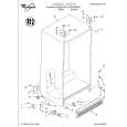
DISASSEMBLY INSTRUCTIONS
1-5: DVD PCB/DVD DECK (Refer to Fig. 1-5) 1. Make the short circuit on the position as shown Fig. 1-5 using a soldering. If you remove the DVD Deck with no soldering, the Laser may be damaged. 2. Unlock the 2 supports 1. 3. Remove the Front Tray Plate in the direction of arrow (A). 4. Disconnect the following connectors: (CP2601, CP2602 and CP2603). 5. Remove the 4 screws 2. 6. Remove the DVD Deck in the direction of arrow (B). 7. Remove the 4 screws 3. 8. Remove the DVD PCB in the direction of arrow (C).
Front Tray Plate Make the short circuit using a soldering.
1 1
(A)
2 2
2
DVD Deck
2
Pick Up PCB
3
(B)
3 3
DVD PCB (C)
3
Deck Angle
Fig. 1-5 NOTE When the installation of the DVD Deck, remove all the soldering on the short circuit position after the connection of Pick Up PCB and DVD PCB connector.
B1-2
|
|
|
> |
|