|
|
|
Categories
|
|
Information
|
|
Featured Product
|
|
|
 |
|
|
There are currently no product reviews.
 ;
Perfect source for service manuals: fast and professional transaction; high quality, perfect readable and largely scaleable PDF; complete schemes, diagrams and spare part list. Tnx a lot, cu again!!!!
;
I got your link from a friend and I must say that I am really satisfied with your service. Specially this B&O manual I didn't find anywhere on the web... but you could deliver it :-) . You deliver very fast and the copy is of good quality. So your webpage is bookmarked. Thanks
;
This was the Sony CCU-500A Service manual I was looking for.
The price was reasonable.
The permission to download was quck.
I will use Owner-Manual.com for all my manual needs.
;
Excellent printing quality.
A complete and very usefull service manual with all details.
GREAT SERVICE AT VERY LOW PRICE!
A+++++++++++++++++++++++++
;
Excellent printing quality.
A complete and very usefull service manual with all details.
GREAT SERVICE AT VERY LOW PRICE!
A+++++++++++++++++++++++++
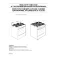
MD-MT290H
� Recording/playback operation.
Insert a low reflection disc, and ascertain audio output by normal playback, and then set TEST REC mode. Change MSL from 00H to 80H by the control setting of EEPROM. After completing the operation, return in to 00H. Does the head move down, failing to start record even when the continuous record mode is set after address ? Yes Does the RF waveform appear at TP201 when recording/ Playback is performed. No Does level of pins 69 of IC401 and pin 2 of change depending on record and playback ? Yes Yes No Check voltage of pins 89 and 90 of IC201, pins 17, 18, 20, and 21 of IC601, pins 8 and 9 of CN601. Check whether disc is record-inhibited.
No
Check periphery of IC401 and IC101.
Is RF pattern output from IC201 pin 36, 37 ? Yes Check whether there is any damage in IC101, periphery of laser diode. Check for defects of IC351 head, flexible PWB.
No
Check for soldering failure of IC201 .
Check whether input waveform is observed on the pins 3 and 4 of IC501. Yes
No
Check whether the audio signal line between IC501 and J701 is defective.
Is the output waveform output to the pin 9 of IC501 ? Yes Check the periphery of IC501 and the waveform of the pins 97, 100, 101, 102 of IC201.
No
Check whether the pin 16 of IC501 and the pin 108 of IC201 are in H state.
� 35 �
|
|
|
> |
|