|
There are currently no product reviews.
 ;
Manual found fast and good quality, very helpfull service
;
8-17-12 Been using the sight for about 6 months. Fast Downloads and top quality
Manuels !
 ;
Everything was great, the manual, the response time, the simplicity of the order, and the
Price. The only thing that I could possible say on a negative note would be that the manual I ordered was more for a service tech. There were a lot of schematic diagrams that didn't help me solve the problem. However I would order again and recommend the web sight to others.
;
I'd been looking for this manual for awhile. Exactly what I needed - and at an excellant price. Thanks!
;
very complete. acceptable resolution. details are a little unclear. is a manual note 8.
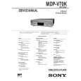
6 Loosen three screws on the spindle motor.
Loosen the screw about a turn from the state of being tight.
Feed base block assembly
Insert a eccentric screwdriver to either one of the hole for adjustment.
Chucking ring
Jig terminal Mode Oscilloscope Phase difference Before adjustment
Hole Hole
: E, F : TRACKING, SLED OFF : X/Y Lissajous's range (Each 20 mV/div.) : 1 : 3 or more 1
Fig. 7-4. 7 Again, plate the CD (YEDS-18) in the playback status. 8 Connect the oscilloscope to the terminals E and F of MD adjustment cable, and turn off the SLED and TRACKING switches. 9 Insert a eccentric screwdriver into the feed base block assembly for RD adjustment. !º After adjustment, turn on the SLED and TRACKING switches. !¡ Remove the CD (YEDS-18), and tighten three screws on the spindle motor, then three screws on the feed base block assembly.
3 or more
Make the figure straight. After adjustment
1
3 or more
Fig. 7-5.
7-3
 $4.99 MDPV70K SONY
Owner's Manual Complete owner's manual in digital format. The manual will be available for download as PDF file aft…
|