|
|
|
Categories
|
|
Information
|
|
Featured Product
|
|
|
 |
|
|
There are currently no product reviews.
 ;
perfect! you just sent to me the copy in Italian witout even my specification!!!! so you are really smart cooperative and efficient. To my opinion the best place all over to get a manual of electronics!!!!
;
Well Well Well!!!! Good manual perfect for my hobby!!! As Before you have done a very well done work!!!! Thank you
;
Super nice! Good to have a manual in digital format.
;
Great job supplying the manual.
Many of these products weerepretty obscure, so it was great that you had
the manual for it!
;
Great manual, would not have been able to operate my machine without it!!
James Dawson August 18, 2012
4-4. Temperature Compensation Offset Adjustment
Save the temperature data at that time in the non-volatile memory as 25 �C reference data. Note : 1. Usually, do not perform this adjustment. 2. Perform this adjustment in an ambient temperature of 22 �C to 28 �C. Perform it immediately after the power is turned on when the internal temperature of the unit is the same as the ambient temperature. 3. When D101 has been replaced, perform this adjustment after the temperature of this part has become the ambient temperature. Adjusting Method : 1. Rotate the AMS knob and display �TEMP ADJUST�. 2. Press the ENTER/YES button and select the �TEMP ADJUST� mode. 3. �TEMP = � and the current temperature data will be displayed. 4. To save the data, press the ENTER/YES button. When not saving the data, press the EDIT/NO button. 5. When the ENTER/YES button is pressed, �TEMP = SAVE� will be displayed for some time, followed by �TEMP ADJUST�. When the EDIT/NO button is pressed, �TEMP ADJUST� will be displayed. Specifications : The �TEMP = � should be within �E0 - EF�, �F0 - FF�, �00 - 0F�, �10 - 1F� and �20 - 2F�.
4-5. Laser Power Adjustment
Connection :
Laser power meter
Optical pick-up objective lens
Digital voltmeter
BD board TP (I + 5V) TP (IOP)
Adjusting Method : 1. Set the laser power meter on the objective lens of the optical pickup. (When it cannot be set properly, press the 0 button or ) button and move the optical pick-up.) Connect the digital volt meter to TP (IOP) and TP (I+5V). 2. Rotate the AMS knob and display �LDPWRADJUST�. (Laser power : For adjustment) 3. Press the ENTER/YES button twice and display �LD $ 4B = 3.5 mW�. 4. Adjust RV102 of the BD board so that the reading of the laser power meter becomes 3.4 +0.1 mW. �0 5. Press the ENTER/YES button and display �LD $ 96 = 7.0 mW�. (Laser power:MO reading) 6. Check that the laser power meter and digital voltmeter readings satisfy the specified value. Specification :
Laser power meter reading : 7.0 ± 0.3 mW Digital voltmeter reading : Optical pick-up displayed value ± 10%
(Optical pick-up label)
KMS
210A 27X40 B0825
lop = 82.5 mA in this case lop (mA) = Digital voltmeter reading (mV)/ 1 (�)
7. Press the ENTER/YES button and display �LD $ 0F = 0.7 mW�. (Laser power: MO reading) 8. Check that the laser power meter at this time satisfies the specified value. Specification :
Laser power meter reading : 0.70 ± 0.1 mW
9. Press the EDIT/NO button and display �LDPWR ADJUST�, and stop laser emission. (The EDIT/NO button is effective at all times to stop the laser emission.)
� 35 �
n
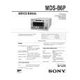 $4.99 MDSB6P SONY
Service Manual Complete service manual in digital format (PDF File). Service manuals usually contains circuit diagr…
|
|
|
> |
|