|
|
|
Categories
|
|
Information
|
|
Featured Product
|
|
|
 |
|
|
There are currently no product reviews.
 ;
Manual was complete. Received it quickly. No problems
;
Product was very good. Received quickly and complete
 ;
The Sony AV-3600 service manual was what I needed for the repair of this unit
Thanks for the good service
Dave
;
I purchased a copy of my old JVC VCR Service manual from Owner-Manuals.com
The copy was complete and valuable to me.
I was able to fix my VCR - it had a bad belt.
I am glad I found Owner-Manuals.com
Great Price. Thanks
;
Great service! I got manual to my sony receiver for very reasonoble price.
MDX-65
THIS NOTE IS COMMON FOR PRINDED WIRING BOARDS AND SCHEMATIC DIAGRAMS. (In addition to this, the necessary note is printed in each block.) for schematic diagrams � All capacitors are in µF unless otherwise noted. pF: µµF 50 WV or less are not indicated except for electrolytics and tantalums. � All resistors are in � and 1/4 W or less unless otherwise specified. � % : indicates tolerance. � C : panel designation. Note: The components identified by mark ! or dotted line with mark ! are critical for safety. Replace only with part number specified. Note: Les composants identifiés par une marque ! sont critiques pour la sécurité. Ne les remplacer que par une piéce portant le numéro spécifié.
4-4. PRINTED WIRING BOARDS � SERVO SECTION �
� U : B+ Line. � Power voltage is dc 14.4V and fed with regulated dc power supply from Master unit. � Voltage and waveforms are dc with respect to ground under no-signal conditions. no mark : PB � : Impossible to measure � Voltages are taken with a VOM (Input impedance 10 M�). Voltage variations may be noted due to normal production tolerances. � Waveforms are taken with a oscilloscope. Voltage variations may be noted due to normal production tolerances. � Circled numbers refer to waveforms. � Signal path. E : PB for printed wiring boards � X : parts extracted from the component side. � Y : parts extracted from the conductor side. � r : Through hole. � b : Pattern from the side which enables seeing. (The other layer�s patterns are not indicated.) Caution: Pattern face side: (Side B) Parts face side: (Side A) Parts on the pattern face side seen from the pattern face are indicated. Parts on the parts face side seen from the parts face are indicated.
� 17 �
� 18 �
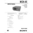 $4.99 MDX65 SONY
Owner's Manual Complete owner's manual in digital format. The manual will be available for download as PDF file aft…
|
|
|
> |
|