|
|
|
Categories
|
|
Information
|
|
Featured Product
|
|
|
 |
|
|
There are currently no product reviews.
 ;
Great manual, thank you, sony kp46s3 service manual perfectly, i am very happy.
;
Complete original Service Manual in good (scan) quality!
;
Very good manual. Plenty of service information including alignment instructions. Clear circuit diagram. Excellent, thank you.
 ;
Good morning, the service manual you sent me was perfect.
Your service and answering are excellent.
I recomend this service.
Best regards.
;
I had been looking everywhere for a proper service manual for this VCR. Everywhere else that has this available for download has a very light version. This is the full service manual with all aspects that would interest anyone looking for the service manual for the AIWA HV-MX100 Worldwide VHS VCR. Great quality (as always). A winner hands down. Best Quality.
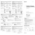
MDX-66XLP SECTION 1 SERVICE NOTE
1-1. TO PLACE THE SET INTO PLAYBACK MODE
The this set has no key control function and cannot be placed into the Playback mode alone. For key control, the this set is controlled through serial communication with a master unit (car audio player, TV tuner or source selector compatible with the Sony BUS system.) To service the this set, the set should be connected as given below:
MDX-66XLP
Master unit
BUS CONTROL OUT
BUS CONTROL IN
1-2. HOW TO CHECK THE SERVO BOARD WAVEFORMS
1. Remove the panel (rear) assy, case (upper) and panel (front) assy. Then, remove the main board from the mechanism deck. (See page 8 of �SECTION 3. DISASSEMBLY�.) 2. Remove the chassis (OP) block from the mechanism deck. (See page 9 of �SECTION 3. DISASSEMBLY�.) 3. Short each bridge points BP1 and BP2 on the main board by solder bridge.
� main board (conductor side) �
BP1 BP2
4. Connect the power board with the main board by the main flexible board. Connect the main board with the servo board by the servo flexible board. 5. Connect to a master unit. With the master unit OFF, press the preset buttons 4 t 5 t 1 (2 seconds or more each) in this turn to enter the TEST mode. 6. Open the doors and insert a disc in the chassis (OP) assy. Use the SOURCE button on the master unit to select to MD to playback. 7. Check the waveforms at each point on the servo board. Note: After this check is completed, remove solder between shorted bridge points BP1 and BP2 and open these points.
3
|
|
|
> |
|