|
There are currently no product reviews.
 ;
I buy the service manual cheaper here than in elsewhere.Am happy with this site. I recommended the Owner-Manuals.com
;
Great Manual. It was exactly what I was looking for
;
Great Manual. It was exactly what I was looking for
;
I am really satisfied. It was ceap, easy and quick. Te owner manual is a full service book. I got what I expected. Thx
;
The service was good but it just a little late for the download. It seems that it needs to clear the payment but the payment was settled by paypal. As far as my concern, it should be able to download after the confirmation of sold.
CX-1020
- Removing the Carriage Motor (2/2)
1. Remove the screw, then remove the Holder. 2. Remove the screw, drive out the Carriage Motor through the direction indicated by the white arrow head.
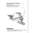
- Removing the Spindle Motor (2/2)
1. Peel off solder provided in the circled position, then remove the lead wire. 2. Remove the three screws, then drive out the Spindle Motor through the direction indicated by the white arrow head. Note: When the PU Unit is installed, it must be moved along the outer perimeter.
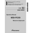
- Removing the Loading Motor (2/2)
1. Peel off solder in the circled position, then remove the Flexible PCB.
2. Remove the four screws, then dismount the Bracket. 3. Remove the four springs. 4. Remove the two screws, then dismount the Motor Bracket. 5. Remove the two screws, then dismount the Loading Motor. When replacement of the Loading Motor is complete, apply 7V to the new Loading Motor with the chassis being assembled (without the MD Unit, though). Then, insert the disk and clamp.
- Why clamping is required
It is difficult to dismount the Chassis Assy from the Upper Case because its move can be blocked by section A in the figure. As long as the machine is in the clamp mode, section A is pulled inside the chassis, thereby allowing you to remove the chassis easier.
|