|
There are currently no product reviews.
 ;
Great quality complete service manual! complete parts list and drawings. Thanks!
;
Great quality complete service manual! complete parts list and drawings. Thanks!
;
Very good quality, prompt response. This website has reasonable prices and wide range of manuals that are hard to find.
;
The document was usefull, and it was exactly what I was looking for.
;
OK?..manual is complet and helpfull... for repairing such a old and rare boombox like JVC PCM it is necessary...
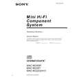
HCD-DX10/RG4SR/RG20/RG30T
CD SECTION
Note :
1. CD Block is basically designed to operate without adjustment. Therefore, check each item in order given. 2. Use YEDS-18 disc (3-702-101-01) unless otherwise indicated. 3. Use an oscilloscope with more than 10M� impedance. 4. Clean the object lens by an applicator with neutral detergent when the signal level is low than specified value with the following checks. RF Level Check
oscilloscope CD board IC751 pin q; GND
Procedure : 1. Connect oscilloscope to pin q; (IC751). 2. Turned Power switch on. 3. Load a disc (YEDS-18) and playback. 4. Confirm that oscilloscope waveform is clear and check RF signal level is correct or not.
Note : Clear RF signal waveform means that the shape � � � can be clearly distinguished at the center of the waveform.
RF signal waveform VOLT/DIV : 200mV TIME/DIV : 500ns
level : 1.4 to 2.1 Vp-p
Adjustment Location: CD board [CD BOARD] (Component Side)
CN732
CN731 TP connected to pin q; (IC751) C746A
CN733
14
|