|
|
|
Categories
|
|
Information
|
|
Featured Product
|
|
|
 |
|
|
There are currently no product reviews.
 ;
This manual was exactly what i needed and could not find elsewhere. Price is not too high. Great !
;
ecelent I was reciver the service manual soon I fell so happy very complete 100% positive all by this store tanks atte Luis salazar
 ;
A great copy of the manual, and the only one I could find anywhere on the net! The circuit diagrams are easily readable, all component values marked and easy to see. A highly appreciated download!
;
Great Manual. This manual is available no where else. It was exactly what I was looking for.
;
The TEAC A-1500's Service Manual was instrumental in reviving this classic reel-to-reel. Not only does it have the schematics, exploded parts diagram and parts list, it also provided mechanical adjustment information that approximate factory default settings.
MJ-D508
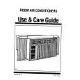
7.1.2 DISASSEMBLY Removal of the Servo Mechanism Assy
1 Remove the screw A and screw B. 2 Disconnect the connectors (CN102, CN103, CN105), open the hook of part A, and tilt the upper side of the CORE MAIN UNIT ASSY to the front. 3 Disconnect the connector (CN101) at the rear of the CORE MAIN UNIT ASSY and remove the CORE MAIN UNIT ASSY. 4 After the Carrier has been pushed in, move the Upper Slider to the rear and stop it at the position where the Under Slider starts to move.
2
CN105 Screw A
2 1
Screw B CN101 CN102
Part A
2 CN103 3
1
CORE MAIN UNIT ASSY
5 Shift part B to the position shown in the figure while raising the Under Slider. (At the same time, the Upper Slider moves to the front.) 6 Remove the Lock Plate. (One screw B)
Under Slider Upper Slider
4
Part B
Screw C
5
7 Remove the Servo Mechanism Assy.
Lock Plate
Servo Mechanism Assy
Caution for the time of installation of the servo mechanism assy
Move the MD Pick-up to the innermost circumference. The servo mechanism assembly is not installed other than the innermost circumference.
6
52
|
|
|
> |
|