|
|
|
Categories
|
|
Information
|
|
Featured Product
|
|
|
 |
|
|
There are currently no product reviews.
 ;
Thanks God for the internet and thanks for the service like this - proffessional solution on time.
;
About the service it's very fast and reliable. About the manual the quality is high enough to read even the tiniest details on the wiring diagrams so you can't ask much more than that, let it alone for a manual of a product from 20 years ago. Thank you, very satisfied.
;
The downloaded quality was as good as the orignial
 ;
This is a great and complete Service Manual for the Sharp GF8585HB. Giving full and detailed technical insight. Good to find these manuals online.
;
Everything was ok with the manual. If I have a small complaint, is that I ordered it during the weekend and I think you guys were closed. But I did receive it late Sunday. I will surely order from you again
MJ-D707, MJ-17D
7.2 DIAGNOSIS
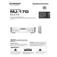
7.2.1 DISASSEMBLY Removal of the Servo Mechanism Assy
1 Remove the screw A. 2 Disconnect the connectors (CN102, CN103, CN105), open the hook of part A, and tilt the upper side of the CORE MAIN UNIT ASSY to the front. CN105 3 Disconnect the connector (CN101) at the rear of the CORE MAIN UNIT ASSY and remove the CORE MAIN UNIT ASSY. 4 After the Carrier has been pushed in, move the Upper Slider to Screw A the rear and stop it at the position where the Under Slider starts to move.
2
CN103
1
2
CN101
Part A
CN102
4
Rear Side
Upper Slider
2
3
CORE MAIN UNIT ASSY
Carrier
Move
5 Shift part B to the position shown in the figure while raising the Under Slider. (At the same time, the Upper Slider moves to the front.) 6 Remove the Lock Plate. (One screw B)
Under Slider
Under Slider Upper Slider
5
Part B
7 Remove the Servo Mechanism Assy.
Screw B
6
Lock Plate
Servo Mechanism Assy
Caution for the time of installation of the servo mechanism assy
Move the MD Pick-up to the innermost circumference. After installation of the servo mechanism assembly, shift the Upper Slider to the rear. (The Under Slider moves at the same time, and the servo mechanism assy is fixed. When the Under Slider is slide, this becomes the reason for switching ring catching.)
7
61
|
|
|
> |
|