|
|
|
Categories
|
|
Information
|
|
Featured Product
|
|
|
 |
|
|
There are currently no product reviews.
 ;
Very good manual. Plenty of service information including alignment instructions. Clear circuit diagram. Excellent, thank you.
 ;
Good morning, the service manual you sent me was perfect.
Your service and answering are excellent.
I recomend this service.
Best regards.
;
I had been looking everywhere for a proper service manual for this VCR. Everywhere else that has this available for download has a very light version. This is the full service manual with all aspects that would interest anyone looking for the service manual for the AIWA HV-MX100 Worldwide VHS VCR. Great quality (as always). A winner hands down. Best Quality.
;
Top quality manual. Covers all aspects you'd expect in a top quality service manual for this Panasonic VHS VCR. The manual resolution is high. Another top quality manual from the only site worth downloading manuals from! If you're looking for a manual for the PV-9662 VHS VCR, this is the one you'll want to get!
;
complete part-lists and pcb layout, schematic diagram is good enlargable,
MJ-D707, MJ-17D
7.2 DIAGNOSIS
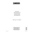
7.2.1 DISASSEMBLY Removal of the Servo Mechanism Assy
1 Remove the screw A. 2 Disconnect the connectors (CN102, CN103, CN105), open the hook of part A, and tilt the upper side of the CORE MAIN UNIT ASSY to the front. CN105 3 Disconnect the connector (CN101) at the rear of the CORE MAIN UNIT ASSY and remove the CORE MAIN UNIT ASSY. 4 After the Carrier has been pushed in, move the Upper Slider to Screw A the rear and stop it at the position where the Under Slider starts to move.
2
CN103
1
2
CN101
Part A
CN102
4
Rear Side
Upper Slider
2
3
CORE MAIN UNIT ASSY
Carrier
Move
5 Shift part B to the position shown in the figure while raising the Under Slider. (At the same time, the Upper Slider moves to the front.) 6 Remove the Lock Plate. (One screw B)
Under Slider
Under Slider Upper Slider
5
Part B
7 Remove the Servo Mechanism Assy.
Screw B
6
Lock Plate
Servo Mechanism Assy
Caution for the time of installation of the servo mechanism assy
Move the MD Pick-up to the innermost circumference. After installation of the servo mechanism assembly, shift the Upper Slider to the rear. (The Under Slider moves at the same time, and the servo mechanism assy is fixed. When the Under Slider is slide, this becomes the reason for switching ring catching.)
7
61
|
|
|
> |
|