|
|
|
Categories
|
|
Information
|
|
Featured Product
|
|
|
 |
|
|
There are currently no product reviews.
 ;
All ok:
Good quality.
Quick response.
Not large price of documents.
Thanks
;
The manual was complete and extremely helpful in both diagnosing the problem I was having as well as fixing it. Excellent quality. I will getting additional manuals in the future.
;
Exactly the JVC service manual and schematics that I was looking for - delivered just hours after order. Will do business again!
;
This is a fantastic site, ad I have been a returning satisfied cusumer!
Thanx for a great sevice!
;
Je suis audiophile belge, électronicien et créateur d'enceintes acoustiques.
J'ai apprécié la qualité des documents fournis. Ils sont très lisibles, ils peuvent être agrandis sans problème et ils sont complets. Pour moi, c'est parfait. Pour cette qualité, je suis d'accord de payer. Et le système de paiement et d'envoi est simple. Merci, continuez comme cela.
Frédéric
MJ-L11
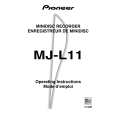
7 Defocus Adjustment
It is possible from steps 3 of this item in the state of step 5 of 6 .
Step No.
1 2 3
Operation Keys and Operation Method
In the Power ON state, selecting MD function,shortcircuit the "MECHA and GNG pin". Insert the test disc GGF1328 (MMD-212). Press the SYSTEM MENU(or MENU) key.(until "deFO AJST" is displayed.) Press the 6(or MD)key. of Defocus Value j
Display
EJECT LOADING GRT AJST deFO AJST PEG : FESpp : of000j0150 Test mode
Status
Remarks
4
Defocus mode is entered, and after automatic execution of normal adjustment.
5 6
Check the jitter value and end the adjustment when the intermediate jitter value is 29 nsec or less. Press the ¶ (REC)of main unit key. of+04 j0130 The C1 error with application of a focus offset of about 0.4µm on the + side is displayed. The jitter value (J+) at this time is recorded. The C1 error with application of a focus offset of about 0.4µm on the � side is displayed. The jitter value (J�) at this time is recorded.
7
Press the ¶ (REC)of main unit key.
of-04 j0120
8
When J+ is larger than J-, press the ¶ (REC) of the main unit key when the focus offset is applied up to +0.4µm. (Do nothig when J- is larger than J+.)
of+04 j0130
9
Change the value with 1 and ¡ keys until the value becomes the same. Press the 6(or MD)key.
of+04 j0132 of+03 j0125 of+02 j0120 COMPLETE
10
When the smaller offset of the jitter value has been corrected mistakenly, press the ENTER(or SET) key and return to step 4. The mean value of the changed set value and the offset of the other setting limit is written into the EEPROM as the compensation offset. Release from the test mode.
11
Turn off the power of the DVD tuner(or CD tuner).
Good Bye
Connection Diagram
Jitter Meter
LEVEL JITTER
MD CORE MAIN UNIT
SIDE A
EFM MON
GND
REFO
36
|
|
|
> |
|