|
|
|
Categories
|
|
Information
|
|
Featured Product
|
|
|
 |
|
|
There are currently no product reviews.
 ;
let's say first that i do not need to have a credit for my opinion, i am a retired sparkie and i voluteerd to fix an electronic device for a local "Youthgroup",as no diagram was present i checked the "net" and gambled on this site and paying some fee via PayPall, i was gladly surprised that the manual arrived as was stated, GOOD SHOW, and best wishes, John
;
I had been looking for a Manual for my CS2150 for quite a while -- in fact I had just about given up. I saw this site and decided to download the Manual. When I Received it by Email I was really pleased with what I got, with the result that My Kenwood 'Scope is now 100% repaired and working well. As an AV Serviceman, you need a good 'scope, and thanks to this site, and the Service Manual, I have been able to repair it. The Manual was a copy of the Factory Original and the copy was very clear, especially in the area of the Circuit Schematics, where You really need to be sure of what You are looking at.
;
I recently purchased a manual for a Samsung DLP tv to help with a trouble shooting problem I was having. Every tv repair shop wanted close to $400.00 for the fix, but after I found Owner-Manuals.com I hit pay dirt. The manual they had for me to purchase and download was a complete service manual for the exact tv I needed. It was complete with wiring diagrams, schematics, and even part numbers. If your the fix it yourself type I highly recommend trying to find any manual here before paying someone else to fix whatever problem your having.
;
Once again, excellent price and manual delivered in a timely manner and as advertised!
;
Outstanding quality manual. This is the exact documentation I needed to service my AKAI GX-210D. This is a PERFECT COPY of the service manual for my machine. Outstanding service. Thank-you!
MJ-L11
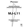
7 Defocus Adjustment
It is possible from steps 3 of this item in the state of step 5 of 6 .
Step No.
1 2 3
Operation Keys and Operation Method
In the Power ON state, selecting MD function,shortcircuit the "MECHA and GNG pin". Insert the test disc GGF1328 (MMD-212). Press the SYSTEM MENU(or MENU) key.(until "deFO AJST" is displayed.) Press the 6(or MD)key. of Defocus Value j
Display
EJECT LOADING GRT AJST deFO AJST PEG : FESpp : of000j0150 Test mode
Status
Remarks
4
Defocus mode is entered, and after automatic execution of normal adjustment.
5 6
Check the jitter value and end the adjustment when the intermediate jitter value is 29 nsec or less. Press the ¶ (REC)of main unit key. of+04 j0130 The C1 error with application of a focus offset of about 0.4µm on the + side is displayed. The jitter value (J+) at this time is recorded. The C1 error with application of a focus offset of about 0.4µm on the � side is displayed. The jitter value (J�) at this time is recorded.
7
Press the ¶ (REC)of main unit key.
of-04 j0120
8
When J+ is larger than J-, press the ¶ (REC) of the main unit key when the focus offset is applied up to +0.4µm. (Do nothig when J- is larger than J+.)
of+04 j0130
9
Change the value with 1 and ¡ keys until the value becomes the same. Press the 6(or MD)key.
of+04 j0132 of+03 j0125 of+02 j0120 COMPLETE
10
When the smaller offset of the jitter value has been corrected mistakenly, press the ENTER(or SET) key and return to step 4. The mean value of the changed set value and the offset of the other setting limit is written into the EEPROM as the compensation offset. Release from the test mode.
11
Turn off the power of the DVD tuner(or CD tuner).
Good Bye
Connection Diagram
Jitter Meter
LEVEL JITTER
MD CORE MAIN UNIT
SIDE A
EFM MON
GND
REFO
36
|
|
|
> |
|