|
|
|
Categories
|
|
Information
|
|
Featured Product
|
|
|
 |
|
|
There are currently no product reviews.
 ;
Excellent printing quality.
A complete and very usefull service manual with all details.
GREAT SERVICE AT VERY LOW PRICE!
A+++++++++++++++++++++++++
;
Pioneer CDXP23S is an old model and has been top useful for me to find this Manual. CD Player is still repaired.
;
Inventory (Stock): a rather extensive list of service manuals, which are hard to find, especially 15+ yrs old.
Pricing: very reasonable.
Delivery/Response: Very Prompt delivery of product: Placed order and received download access within 1.5hrs.
Service Manual: a rather complete OEM service manual (15.5MB pdf file size). Scan quality was very good, accept for a few circuit board diagrams that were dark; Zooming, however, clarified the image. Has the required information for servicing the LD Player.
;
Perfect copy of a necessary document and my Sonic Modulator is repaired!
;
Excellent replacement for original Manual. Worth every cent ! I am totally satisfied!
Alignment and Adjustments
Alignment and Adjustments
2. Cassette Deck
2-1. To Adjust Tape Speed
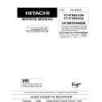
Notes 1) Measuring tape: i) MTT-111 (or equivalent) (Tapes recorded with 3kHz) ii) MTT-5512 (or equivalent) 2) Connect the SPK OUT of the MAIN PCB to the frequency counter as in figure 1-5.
MAIN PCB SPK OUT output Figure 1-5 Frequency Counter
2-2. To Adjust PlayBack Level/REC
Notes 1) Before the actual adjustment, clean the play/recording head. 2) Measuring tape : i) MTT-114N(or equivalent 10kHz AZIMUTH control) ii) MTT-5512 3) The cassette deck is connections as shown in figure 1-7.
Step
Item
Pre-Setup Condition
Pre-Setup 1) Deck :MTT-111 2) Press PLAY SW button
To Adjust
Standard
Remark
1. Adjust Deck 1 Play Level
Fixed 3KHz ±1% range Step Item Pre-Setup Condition Pre-Setup After putting MTT114N into Deck 1 - Press FWD PLAY button. To Adjust Standard Remark
1
NOR SPEED Control
SPK OUT (connected to the frequency counter)
1
Recording /Play head MAIN PCB
SPK OUT
VTVM
AZIMUTH
SPK OUT (VTVM is connected to the scope)
- Turn the control screw to as shown in Figure 1-6.
Max output and same phase (both channels)
After adjustment secure it with REGION LOCK.
Oscilloscope
(GND)
In Out Figure 1-7
2. Adjust Deck 2 Play Level/ REC BIAS
Step Item Pre-Setup Condition
SPK OUT
AZIMUTH control screw
(RVS Play)
AZIMUTH control screw
(FWD Play)
Pre-Setup After putting MTT114N into Deck 2 - Press FWD PLAY button.
To Adjust
Standard
Remark
Figure 1-6
1 AZIMUTH
(VTVM is connected to the scope)
- Turn the control screw to as shown in Figure 1-6.
MAX OUTPUT and same phase (both channels)
After adjustment secure it with REGION LOCK.
Audio OSC.
SET (MAIN PCB)
VTVM
Oscilloscope
After putting MTT-
2
IN AUX IN TP SPK OUT
Recording Bias Voltage
Fig 1-8
5512 into Deck 2
1) Press REC PLAY button. 2) TAPE PCB JCW3 ,connected
- Turn JSR2L,JSR2R to the right and left
CHECK TO 7mV(±0.5mV)
IN OUT
to VTVM
Figure 1-8
1-2
Samsung Electronics
|
|
|
> |
|