|
|
|
Categories
|
|
Information
|
|
Featured Product
|
|
|
 |
|
|
There are currently no product reviews.
 ;
Speedy transaction with a quick download. Awesome hassle-free service.
;
very poolite and healpful secure transaction thanks allot
;
- Very good scan quality, PERFECT!
- Sehr gute scan Qualitaet, empfehlenswert!
Wolfgang Sundhaus
 ;
Good site, works ok and you get what you order, no problems experienced, got my manual within a day. A++++
;
Original well scanned manual. Got the job done. Microwave problem found & corrected. For $5 and a new magnitron from ebay, it was a cheap and good the first shot fix. Electrical schematics allowed me to mage sure every thing else was ok before cutting and order for parts. Hard to live without.
MECHANICAL ADJUSTMENTS
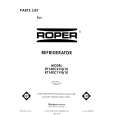
2-2: CONFIRMATION AND ADJUSTMENT OF AUDIO/ CONTROL HEAD When the Tape Running Mechanism does not work well, adjust the following items. 1. Playback the VHS Alignment Tape. 2. Confirm that the reflected picture of stamp mark is appeared on the tape prior to P4 Post as shown in Fig. 2-2-A. a) When the reflected picture is distorted, turn the screw 1 clockwise until the distortion is disappeared. b) When the reflected picture is not distorted, turn the screw 1 counterclockwise until little distortion is appeared, then adjust the a). 3. Turn the screw 2 to set the audio level to maximum. 4. Confirm that the bottom of the Audio/ Control Head and the bottom of the tape is shown in Fig. 2-2-C. c) When the height is not correct, turn the screw 3 to adjust the height. Then, adjust the 1~3 again.
Audio/Control Head Reflected picture of Stamp Mark P4 Post (1) CH-3 Audio (2) Envelope
2-3: TAPE RUNNING ADJUSTMENT (X VALUE ADJUSTMENT) 1. Confirm and adjust the height of the Reel Disk. (Refer to item 1-1) 2. Confirm and adjust the position of the Tension Post. (Refer to item 1-2) 3. Adjust the Guide Roller. (Refer to item 2-1) 4. Confirm and adjust the Audio/Control Head. (Refer to item 2-2) 5. Connect CH-1 of the oscilloscope to TP4001, CH-2 to TP1002 and CH-3 to HOT side of Audio Out Jack. 6. Playback the VHS Alignment Tape. 7. Press and hold the Tracking-Auto button on the remote control more than 2 seconds to set tracking to center. 8. Set the X Value adjustment driver (JG153) to the 4 of Fig. 2-2-B. Adjust X value so that the envelope waveform output becomes maximum. Check if the relation between Audio and Envelope waveform becomes (1) or (2) of Fig. 2-3.
Fig. 2-3
Stamp Mark
Fig. 2-2-A
Audio/Control Head
3
1
2 4
Fig. 2-2-B
Audio/Control Head Tape
0.25±0.05mm
Fig. 2-2-C
|
|
|
> |
|