|
|
|
Categories
|
|
Information
|
|
Featured Product
|
|
|
 |
|
|
There are currently no product reviews.
 ;
Quick delivery, the document was usefull, although the copy was i little bit unclear in the details.
 ;
A complete and well done copy of the manual, at a not expansive price!
The delivery of the manual is very fast.
Thank you for all
;
Perfect quality. Was able to fix speed drifting on my Sansui Turntable using the service manual instructions for PLL adjustment.
;
I am very happy regarding the online purchase of this manual from Owner-Manuals.com as with this I could set right my Denon CD player and Amplifier.
I once again sincerely thank them for the prompt service which was rendered to me.
N. Shanker
;
More than pleased with my prurchase, very good product for the price.
MECHANICAL ADJUSTMENTS
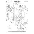
2-2: CONFIRMATION AND ADJUSTMENT OF AUDIO/ CONTROL HEAD When the Tape Running Mechanism does not work well, adjust the following items. 1. Playback the VHS Alignment Tape. 2. Confirm that the reflected picture of stamp mark is appeared on the tape prior to P4 Cap as shown in Fig. 22-A. When the reflected picture is distorted, turn the screw a) 1 clockwise until the distortion is disappeared. When the reflected picture is not distorted, turn the b) screw 1 counterclockwise until little distortion is appeared, then adjust the a). 3. Turn the screw 2 to set the audio level to maximum. 4. Confirm that the bottom of the Audio/ Control Head and the bottom of the tape is shown in Fig. 2-2-C. c) When the height is not correct, turn the screw 3 to adjust the height. Then, adjust the 1~3 again.
Audio/Control Head Reflected picture of Stamp Mark P4 Cap (1) CH-3 Audio (2) Envelope
2-3: TAPE RUNNING ADJUSTMENT (X VALUE ADJUSTMENT) 1. Confirm and adjust the height of the Reel Disk. (Refer to item 1-1) 2. Confirm and adjust the position of the Tension Post. (Refer to item 1-2) 3. Adjust the Guide Roller. (Refer to item 2-1) 4. Confirm and adjust the Audio/Control Head. (Refer to item 2-2) 5. Connect CH-1 of the oscilloscope to TP1002, CH-2 to TP4001 and CH-3 to pin 1 of CP1003. 6. Playback the VHS Alignment Tape. 7. Press and hold the Tracking-Auto button on the remote control more than 2 seconds to set tracking to center. 8. Set the X Value adjustment driver (JG153) to the 4 of Fig. 2-2-B. Adjust X value so that the envelope waveform output becomes maximum. Check if the relation between Audio and Envelope waveform becomes (1) or (2) of Fig. 2-3.
Fig. 2-3
Stamp Mark
Fig. 2-2-A
Audio/Control Head
3
1
2 4
Fig. 2-2-B
Audio/Control Head Tape
0.25±0.05mm
Fig. 2-2-C
D2-3
|
|
|
> |
|